theycallmevirgo
- 108
- 25
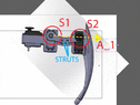
The below is a leg assembly from the Antdroid open source hexapod robot (https://github.com/antdroid-hexapod/antdroid). The "femur" assembly connects the servos at S1 and S2. It is comprised of two side plates connected by cylindrical struts.
Being fundamentally lazy, I prefer to redesign this to be 3d printed as one unit. Obviously, the most likely way to cause destructive deformation is to rotate one end about central axis A_1 while holding the other end fixed. Strain along coplanar vertical axis is not in my opinion worth considering.
The question is, simply, how should I approach the design of the strut? Should I create a solid on a plane between the servo mounts, or should I create a solid that conforms to the plate arc? Either way, can I safely semove some part of the solid to save material? If so, at the center or at the edges?
If my explanations are unclear I will post images of alternatives later.
I have access to some decent software to study the stress reactions. I'm asking here so I can understand which results are "reasonable". Of course I will post outputs here.