How does the thickness of a beam splitter affect the phase shift produced?

Join the discussion
Ask a follow-up here, or get your own question answered by working scientists, mathematicians and engineers — people, not an autocomplete.
Real named experts · corrections over time · the nuance an AI answer skips
4 replies · 5K views
confused_man
Messages
15
Reaction score
1
I'm having trouble understanding the phase shift produced by a beam splitter. I seem to be finding conflicting information.

I'm specifically looking to understand a 50/50 beam splitter where one side has a dielectric mirror, as shown in this figure from wikipedia:
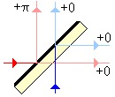
Wavesplitter1.gif


I understand the pi phase shift (due to air/dielectric reflection, where n_air < n_dielectric). Why doesn't the thickness of the beam splitter have any effect? Shouldn't there be an additional phase?

On a related note, I'm trying to see how such a beam splitter would be able to act like a Hadamard gate in quantum information, if the additional phase shift due to the thickness of the plate is included. I've seen many articles/documents say that a beam splitter can implement a Hadamard gate, but this only seems to work if the thickness of the splitter is ignored. What am I missing?

Thank you for any insight.
 

Attachments

  • Wavesplitter1.gif
    Wavesplitter1.gif
    924 bytes · Views: 1,858
Physics news on Phys.org
confused_man said:
I'm having trouble understanding the phase shift produced by a beam splitter. I seem to be finding conflicting information.

I'm specifically looking to understand a 50/50 beam splitter where one side has a dielectric mirror, as shown in this figure from wikipedia:
View attachment 223275

I understand the pi phase shift (due to air/dielectric reflection, where n_air < n_dielectric). Why doesn't the thickness of the beam splitter have any effect? Shouldn't there be an additional phase?

On a related note, I'm trying to see how such a beam splitter would be able to act like a Hadamard gate in quantum information, if the additional phase shift due to the thickness of the plate is included. I've seen many articles/documents say that a beam splitter can implement a Hadamard gate, but this only seems to work if the thickness of the splitter is ignored. What am I missing?

Thank you for any insight.

The phase shift of the reflected beam can be compensated by putting a phase-shifter in the transmtted beam.

To make a Hadamard gate the outputs from the input state |0>|1> must be recombined in a second BS to give (|0>|1>+i|1>|0>)√2
 
Last edited:
Thank you for the reply. What about the phase shift due in the transmitted beam due to the plate thickness? This is the one that I am confused about, as it seems that many sources just ignore the fact that the beam splitter has some finite width, which would introduce some additional phase shift in the transmitted and reflected blue beams. I don't see how you could compensate for this.
 
confused_man said:
Thank you for the reply. What about the phase shift due in the transmitted beam due to the plate thickness? This is the one that I am confused about, as it seems that many sources just ignore the fact that the beam splitter has some finite width, which would introduce some additional phase shift in the transmitted and reflected blue beams. I don't see how you could compensate for this.
There is another recent post dealing with this but I cannot find it. Try searching posts in the last 3 months.
 
Most texts do not discuss the phase shift introduced by the dimensions of the crystal because it does not matter. Let us consider all possible phase deviations. Let [itex]\phi_0[/itex] be th einitial phase difference between the red and the blue beam, [itex]\phi[/itex] the phase shift introduced by the beam splitter width from the reflecting surface to the right and [itex]\phi'[/itex] the phase shift due to light going from the lower surface to the reflecting surface.
For the for beams you will find the following phases:
red one from the left to the top: [itex]\phi_0+\pi[/itex]
blue one from bottom to top: [itex]\phi'[/itex]
red one from the left to the right: [itex]\phi_0+\phi[/itex]
blue one from the bottom to the right: [itex]\phi+\phi'[/itex]

Now the first thing that matters is the phase difference at the output ports:
top: [itex]\phi_0+\pi-\phi'[/itex]
right:[itex]\phi_0+\phi-\phi-\phi'=\phi_0-\phi'[/itex]

Now the final quantity of interest is the phase difference of these differences and as you can see, this will always be [itex]\pi[/itex] regardless of how the other parameters are chosen.
 
  • Like
Likes   Reactions: Derek P, DrChinese and Mentz114