Discussion Overview
The discussion revolves around the design of an H-bridge circuit using IR2103 half-bridges to generate a 55V AC signal at 50Hz for exciting a transformer. The participants explore the technical aspects of the circuit design, safety concerns, and alternative solutions.
Discussion Character
- Technical explanation
- Debate/contested
- Experimental/applied
Main Points Raised
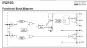
- One participant seeks guidance on creating an H-bridge setup to reverse polarity at 50Hz using IR2103 and Arduino.
- Concerns are raised about the dangers of working with high voltages, with one participant emphasizing the need for proper training and understanding of the manufacturer's datasheet.
- Another participant expresses frustration over perceived reluctance to share knowledge, asking for clarification on specific terms like "UV" and "dead time."
- There is a suggestion to simulate the circuit using LTspice to better understand its operation.
- A participant questions the feasibility of the transformer design, suggesting that the turns ratio may lead to excessive resistance.
- One participant proposes the idea of purchasing an inverter that can handle a 55V input as an alternative solution.
- Another participant emphasizes the importance of knowing the current draw from the 55V supply before proceeding with the design or purchase of an inverter.
- Discussion includes practical measurements and checks that the original poster plans to conduct to ensure safe operation of the circuit.
Areas of Agreement / Disagreement
Participants express differing views on safety and the ability of the original poster to handle the project. While some emphasize caution and the need for experience, others focus on technical details and potential solutions. The discussion remains unresolved regarding the best approach to take.
Contextual Notes
Participants highlight the need for a clear understanding of electrical safety and the implications of working with high voltages. There are references to previous discussions being paused, indicating ongoing concerns about the original poster's approach.