Locking gear on container doors

3 replies · 2K views · last reply
Optymista93
Messages
6
Reaction score
2
Hi there,
I would like to use Your expertise in solving one of the challenges I've faced right now, as an intern.

My task is to design steel container doors and its locking system. As it's a light container, locking system should be placed inside of the doors. To visualize, the container and doors looks like this. Among other things, I need to consider "gasket rubbers" (not sure if it's a right English Word for it) around the doors, extream overload caused by the weather & weaves on the ocean etc.
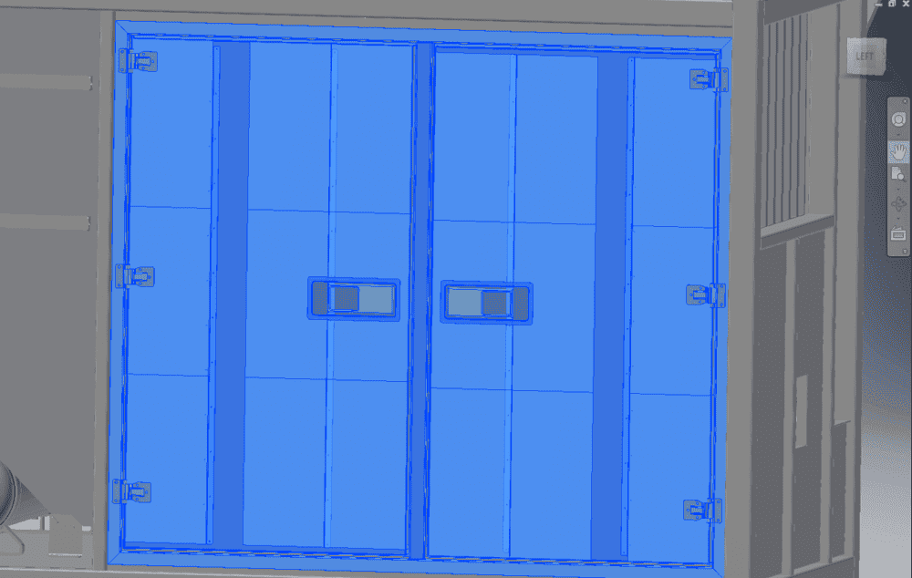
CAD render of a pair of double steel container doors, shown in blue highlight, with hinges on the outer edges and a small handle or lock fitting on each door, beside the grey container body.


I'll be using locking system similar to one on the images below.
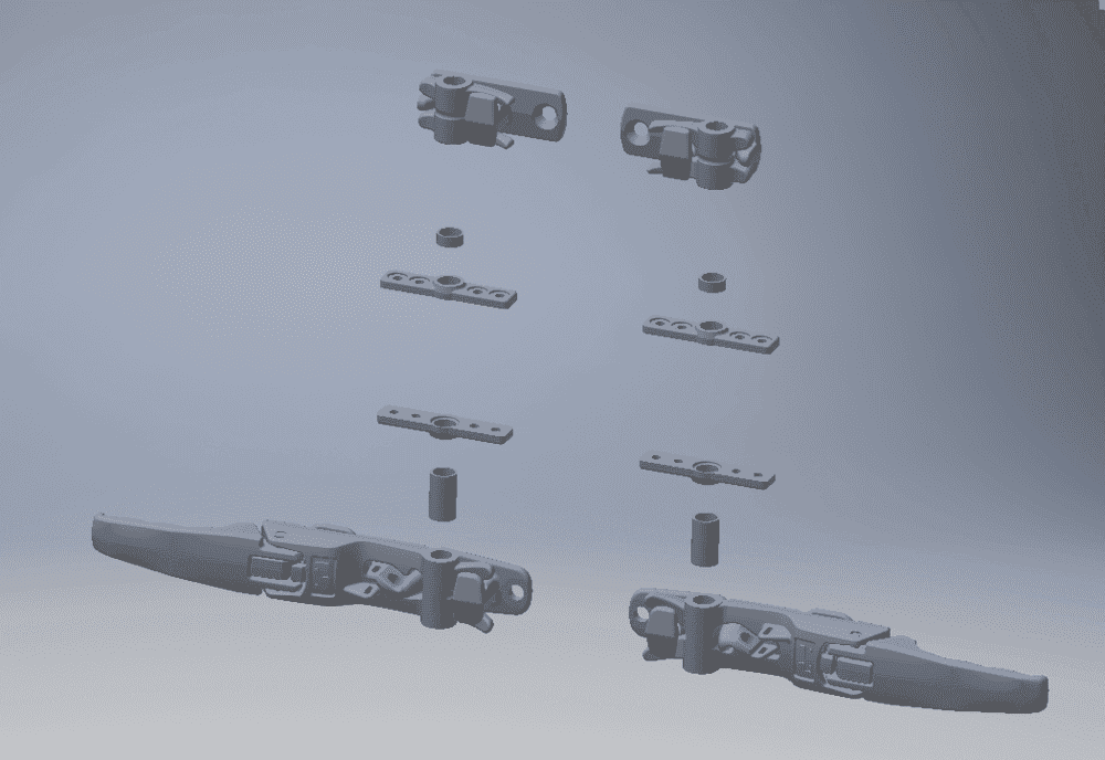
Exploded CAD view of a container door locking system: two rod-end hinge brackets at top, two spacer bushings, two flat mounting plates, two tubular spacers, and two long handle-and-latch lock bars at bottom.
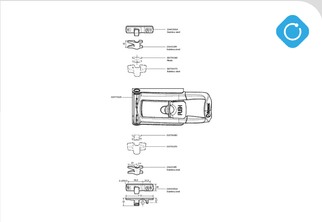
Exploded technical drawing of a container door locking mechanism with part numbers and materials, including stainless steel and plastic fixing plates and a central lock body.


My issue is that I can't figure out how to fasten the lock's fixing to the container and keep the doors sealed.
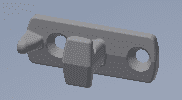
Grey 3D CAD render of a container door locking fitting: a flat bar with a rounded lug, a circular hole at each end, and a raised rectangular block in the centre.

Lock's fixingJust to visualize a bit more.
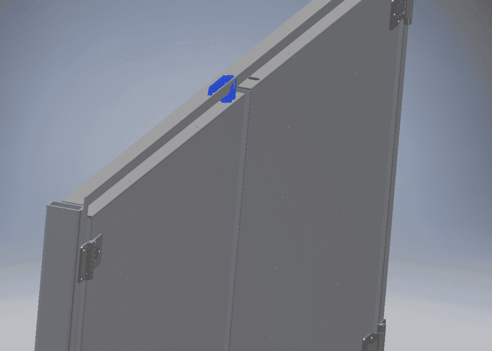
CAD render of two steel container doors in closed position, with a blue locking bar mechanism at the top edge and hinges on the outer edges.
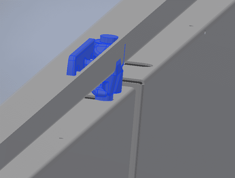
CAD render of a container door edge showing blue locking cam fittings mounted on the door frame, with a raised rectangular lip and a recessed seal channel running along the edge.


Door frame is adjustable, because we are producing the doors. However, how to keep it sealed ("gasket rubbers") and make it not interfere with the frame?

I would really appreciate all the input.

Thanks in advance,
Dan
 
Welcome to PF.

When closed, the rectangular doors fit in the end frame of the container and give it greater strength during transport.

There are usually four claws on each door, eight in all.
When the locking claws are rotated, the doors are pulled into clamp the rubber seals.

The force needed to close a container door seal is very high. It requires a long lever to apply that force. I don't think the lock/catch you picture will make it possible to close the container.

You show the hinges with fastners exposed when the doors are closed. You need to change that so the hinge plates are hidden. The fixed hinge pins can be outside.

Have you operated container doors? Is there a container you can practice on, to estimate the forces involved ?
 
  • Like
Likes   Reactions: Optymista93
Thank You for Your reply Baluncore.

Baluncore said:
Have you operated container doors? Is there a container you can practice on, to estimate the forces involved ?

Yes, we have complete containers in the workshop, so I can estimate approximate forces involved.
However, all the containers have locking gear on the outside of the doors and not, as in this case, on the inside.

Baluncore said:
You show the hinges with fastners exposed when the doors are closed. You need to change that so the hinge plates are hidden. The fixed hinge pins can be outside.

Don't worry about the hinges, it's just a 'sketch' and probably not the ones i'll eventually using.
My issue is that I can't figure out how to fix locking systems keeper (thing that keep claws in a place, when the door is shut) to the frame, so it doesn't interfere with the doors frame. There are two things I've thought about. First is to make a cutout in the actuall door frame. Second is to make a frame longer (vertically), so that the keeper and claws can be positioned between the doors top and the frame. However, this second solution would make rubber seals useless on both top and the bottom. In addition, I have little space to maneuver with. (36mm from the frames top to the container structure and only 20mm on the bottom.)
CAD render of a container door frame with a blue plane marked and a dimension line labelled 36,000 mm running from the frame top to the container structure.
 
Optymista93 said:
However, all the containers have locking gear on the outside of the doors and not, as in this case, on the inside.
You need to look at a container door from the outside while imagining you are inside.
The usual long lever arms give maybe a factor of 10 advantage when rotating the cams/claws. How can you get a similar advantage with the shorter lock.
If the control bars are inside the container they may be jammed by a spilled load. They must be protected in the door panel.

Have you considered a bi-fold door that has hinges on one side and in the middle. The middle of the door closes last, after the sides are held in channels.