I Magnetic Component Permeability vs Frequency Loss

AI Thread Summary
The discussion centers on the relationship between magnetic permeability, frequency losses, and material choices for electromagnetic applications, particularly comparing powdered metals like MPP and Sendust with Metglas. Higher permeability materials tend to have lower frequency losses and skin depth, impacting efficiency at specific frequencies like 5 kHz and field strengths around 1 Tesla. Participants emphasize the importance of considering the geometry and design of the magnetic circuit, as well as the trade-offs between permeability, inductance, and the number of turns in the winding. Ultimately, the consensus leans towards using powdered materials for higher inductance and stronger fields, despite potential increases in resistance and voltage requirements. Understanding the specific application and requirements is crucial for selecting the appropriate material.
Sibilo
Messages
65
Reaction score
2
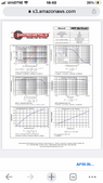
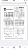
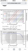
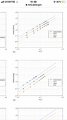
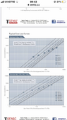
As per the title, I am unable to understand the relationship between relative permeability and frequency losses of some materials. Considering metals in powder form such as (mpp, sendust and high flux) and metglas (amorphous). Why does the density also increase in powders (mpp, sendust, high flux) as the permeability increases? Why does increasing the permeability (14, 26, 60) decrease the parasitic frequency losses? And then why does the working frequency increase at lower permeabilities. Here, to conclude, metglas has a unique permeability, namely 1,000,000, but therefore at the same frequency and field (10 khz, 1 T) does metglas have fewer losses than powders, or vice versa? My aim is to know which of all these materials has the lowest losses and is more efficient at 10 khz and 1 Tesla, or similar values. I attach images in particular of the different permeabilities of the powders
 

Attachments

  • 7745DC28-4A91-498A-B926-A512D8B4711B.png
    7745DC28-4A91-498A-B926-A512D8B4711B.png
    33.5 KB · Views: 41
  • 20377A48-70A0-44B3-9BA7-94285FD34A96.png
    20377A48-70A0-44B3-9BA7-94285FD34A96.png
    31.9 KB · Views: 25
  • B9CAF895-6A59-4A86-8A47-171EF7210EE7.png
    B9CAF895-6A59-4A86-8A47-171EF7210EE7.png
    28.3 KB · Views: 45
  • C114E4F9-DB52-4BE4-BF1F-D02B37665305.png
    C114E4F9-DB52-4BE4-BF1F-D02B37665305.png
    16.1 KB · Views: 30
  • FDFCA08A-0D8D-44FD-9C74-0710D861B7E1.png
    FDFCA08A-0D8D-44FD-9C74-0710D861B7E1.png
    16 KB · Views: 30
  • 71A0857C-EB39-4E10-837C-7AB17D6B917C.png
    71A0857C-EB39-4E10-837C-7AB17D6B917C.png
    37.3 KB · Views: 34
  • F4056C00-EB39-40D5-AA65-C75337B19A9E.png
    F4056C00-EB39-40D5-AA65-C75337B19A9E.png
    19.2 KB · Views: 29
  • 17D22005-DCD9-4ADA-8750-340408BD18A8.png
    17D22005-DCD9-4ADA-8750-340408BD18A8.png
    34.5 KB · Views: 31
Physics news on Phys.org
You want to use these materials in a 1T static field?
 
  • Like
Likes Sibilo, DaveE and berkeman
Analyse the skin effect depth in the material. Note the particle size.
Skin depth; d = √( (2 · r ) / ( ω · μ ) )
r = resistivity; μ = permeability; ω = angular freq = 2·π·fHz .
https://en.wikipedia.org/wiki/Skin_effect#Formula

Since; d ∝ √ 1/μ ; the highest permeability is often associated with the least skin depth.

Energy that propagates beyond skin depth is lost from the external field, to become heat.

Higher frequencies require smaller magnetic particles, separated by more of the lower density ceramic, glass or resin.
 
Last edited:
Sibilo said:
Why does the density also increase in powders (mpp, sendust, high flux) as the permeability increases?
Because the air in between the metal bits has very low permeability and low density?

Sibilo said:
then why does the working frequency increase at lower permeabilities.
Because the "working frequency" is essentially defined by the losses?

Sibilo said:
metglas has a unique permeability, namely 1,000,000,
Wait, I've been out of this game for a few decades. Metglas is a tape core, right? Are you really comparing a tape core to a powdered core? Or did I miss something. Powdered cores have a lot of air gaps built in. Don't confuse basic material properties with core properties.

Back in my day, Metglas was expensive and really good in many ways. You get what you pay for. Plus, don't confuse magnetic parameters of the material with the parameters of a constructed core. How would you get a relative permeability of 14 or 26 with a material that intrinsically has much higher permeability?

Sorry, I'm too lazy to open 8 data sheet graphs, but...
1 Tesla? Really? This is news to me (again, I haven't been paying attention). Which materials can handle 1 T without saturation?
 
Last edited:
  • Like
Likes Sibilo and berkeman
marcusl said:
You want to use these materials in a 1T static field?
no no absolutely the field will have a frequency of 5 khz or higher, it depends on the design
 
Baluncore said:
Analyse the skin effect depth in the material. Note the particle size.
Skin depth; d = √( (2 · r ) / ( ω · μ ) )
r = resistivity; μ = permeability; ω = angular freq = 2·π·fHz .
https://en.wikipedia.org/wiki/Skin_effect#Formula

Since; d ∝ √ 1/μ ; the highest permeability is often associated with the least skin depth.

Energy that propagates beyond skin depth is lost from the external field, to become heat.

Higher frequencies require smaller magnetic particles, separated by more of the lower density ceramic, glass or resin.
eh indeed yes, a permeability of 14 is too low and I would have to make too many turns and therefore increase the inductance, and having a high inductance and high frequency, increases the reactance, therefore the permeability must be high, only that for example for the mpp it reaches a maximum of 500 while for the metglas it reaches more than 10,000 so in your opinion is it better for me to use the metglas? does it also have lower losses?
 
DaveE said:
Because the air in between the metal bits has very low permeability and low density?


Because the "working frequency" is essentially defined by the losses?


Wait, I've been out of this game for a few decades. Metglas is a tape core, right? Are you really comparing a tape core to a powdered core? Or did I miss something. Powdered cores have a lot of air gaps built in. Don't confuse basic material properties with core properties.

Back in my day, Metglas was expensive and really good in many ways. You get what you pay for. Plus, don't confuse magnetic parameters of the material with the parameters of a constructed core. How would you get a relative permeability of 14 or 26 with a material that intrinsically has much higher permeability?

Sorry, I'm too lazy to open 8 data sheet graphs, but...
1 Tesla? Really? This is news to me (again, I haven't been paying attention). Which materials can handle 1 T without saturation?
Hi Dave, on mouser they sell metglas (microlite) magnetic cores and they don't cost much, it has a high permeability compared to powders (mpp) also metglas is an amorphous metal. maybe for the tapes you are confusing it with mumetal, used for shielding. in the technical sheets it is confirmed several times that the saturation of a particular metglas alloy is 1.4 tesla, the section at which this happens is not written, but I think it can be contained with high frequencies. so what do you recommend between metglas and powders, considering the difference in permeability, for me the answer is very important
 
DaveE said:
Sorry, in advance, I'm guessing about your knowledge of this subject. But, I'd suggest reading some about magnetic circuits, reluctance, the effect of air gaps in core design, etc.

https://eng.libretexts.org/Bookshelves/Electrical_Engineering/Electronics/DC_Electrical_Circuit_Analysis_-_A_Practical_Approach_(Fiore)/10:_Magnetic_Circuits_and_Transformers/10.3:_Magnetic_Circuits
have read a lot about these topics, only I would like the most correct answer between metglas and powders (mpp or sendust) which is the best with lower losses at frequencies of >5 khz and high induction fields >1 tesla?
 
  • #10
Sibilo said:
so in your opinion is it better for me to use the metglas? does it also have lower losses?
You are reasoning around in circles. Instead, you must build or simulate the inductor using available materials and measure the inductance and losses.

When you get it right, the windings will heat at the same rate as the magnetic material. If it all gets too hot, make it all bigger.

Inductance is proportional to permeability.
Twice the turns gives four times the inductance.
Why complain about too many turns?
Do you want inductance or do you not want inductance.

Maybe if you explained what the device was for, and you specified the operating parameters, we would be able to identify an efficient design strategy.
 
  • #11
You sound confused. Frequency, applied field strength and induced magnetization are all entirely different quantities. Why are you driving your materials to 1T? What is your applied field strength? How much loss can your application tolerate? Asking “what is best” without understanding your application (let alone anything cores and electromagnetism) is not going to get you anywhere productive .
 
  • Like
Likes Sibilo and DaveE
  • #12
Baluncore said:
You are reasoning around in circles. Instead, you must build or simulate the inductor using available materials and measure the inductance and losses.

When you get it right, the windings will heat at the same rate as the magnetic material. If it all gets too hot, make it all bigger.

Inductance is proportional to permeability.
Twice the turns gives four times the inductance.
Why complain about too many turns?
Do you want inductance or do you not want inductance.

Maybe if you explained what the device was for, and you specified the operating parameters, we would be able to identify an efficient design strategy.
sorry if I answer you after a long time but I did not have the connection, then assuming that I wanted to reach a magnetic field induction of 1 T and a frequency of 5 khz or higher, here if I use the powders (sendust, mpp) they have low permeability max 505, and this would allow me to return within the terms of the saturation of 1 T. instead the metglas has a lot of permeability even more than 50,000 and this would lead me to have few turns and therefore little field transmitted at a short distance. furthermore the inductance is also linked to the frequency for this by increasing the frequency I can decrease the inductance (dimensions), so having said that, considering that the metglas has too high values and perhaps its only use is transformers, then also for an electromagnet would you choose the powders? as for the inductance, I need the device to try to transfer energy (a few cm) and therefore the inductance should be low so as not to contrast too much with the frequency, so I determine the inductance from the frequency. for the losses I had already posted the graphs. here, what do you think, do I have to correct something?
 
  • #13
marcusl said:
You sound confused. Frequency, applied field strength and induced magnetization are all entirely different quantities. Why are you driving your materials to 1T? What is your applied field strength? How much loss can your application tolerate? Asking “what is best” without understanding your application (let alone anything cores and electromagnetism) is not going to get you anywhere productive .
my goal is the transfer of energy at educational level, the currents should be around 10 amps, the losses are those characteristic of the magnetic core (dust)
 
  • #14
Sibilo said:
... my goal is the transfer of energy at educational level, the currents should be around 10 amps, ...
Are you building a transformer with an unusual shape?
What is the geometry of the magnetic circuit?
 
  • #15
Baluncore said:
Are you building a transformer with an unusual shape?
What is the geometry of the magnetic circuit?
no it is absolutely not a transformer, there is only one winding so it is an electromagnet with a magnetic core, the shape is cylindrical, since if I had chosen the toroidal one I would have had the field confined inside, it is a simple electromagnet.however I really believe that, doing the calculations, the powders are the best choice considering the permeability, and I could get to have about 200 or 300 turns, which would create a very strong field, while if I used the metglas from the calculations I had to use about 40 or 50 turns, and therefore the field would be lower. obviously choosing the powders, I would have to make more turns and therefore increase the resistance, and therefore increase the voltage. what do you think, would you also use the powders as a magnetic core to have a stronger field with more turns?
 
  • #16
The magnetic circuit determines the allocation of magnetic material.
As an electro-magnet, what is the field geometry, and what will the field be doing?
Is there a big air gap somewhere?

B will be proportional to amp⋅turns/area of the coil.
Current will be limited by XL and R of the coil.

What is the RMS voltage of the 5 kHz supply?
How much current can the supply provide?
 
  • Like
Likes Sibilo and DaveE
  • #17
Sibilo said:
my goal is the transfer of energy at educational level, the currents should be around 10 amps, the losses are those characteristic of the magnetic core (dust)
Getting information from you about your application is painful and you are approaching your problem backwards by focusing on choosing a component first rather than by defining the requirements of your system, which will then drive component choice. I am signing off. I wish you luck.
 
  • Like
Likes berkeman, Sibilo, DaveE and 1 other person
  • #18
Baluncore said:
The magnetic circuit determines the allocation of magnetic material.
As an electro-magnet, what is the field geometry, and what will the field be doing?
Is there a big air gap somewhere?

B will be proportional to amp⋅turns/area of the coil.
Current will be limited by XL and R of the coil.

What is the RMS voltage of the 5 kHz supply?
How much current can the supply provide?
thanks as always for your answers, you are very kind, yes of course the electromagnet does not have a real air gap since it is an open circuit, it is a cylindrical bar. obviously B must be proportional to the density of turns, now I do not remember the value of H, but I think around 2500 ampere turns / meter. yes of course, the current will be limited by the internal resistance of the coil, but the value is still to be determined precisely after having chosen the frequency with certainty, 5 khz is an arbitrary value so as not to increase too much and have problems with the magnetic core, so when I have chosen the material of the magnetic core, I will choose the right frequency based on the saturation of the material. the effective voltage (rms) must also be chosen based on the resistance of the coil, so I must necessarily choose the material of the magnetic core to determine frequency and voltage, that's why I ask you, so which between metglas and powders, is the best choice? also considering the permeabilities?
 
  • #19
marcusl said:
Getting information from you about your application is painful and you are approaching your problem backwards by focusing on choosing a component first rather than by defining the requirements of your system, which will then drive component choice. I am signing off. I wish you luck.
marcusl I'm sorry you want to abandon me, I wrote a very complete answer to Baluncore, it could help you understand my electromagnet better, I would just like to know which magnetic core material to choose between metglas and powders
 
  • #20
Sibilo said:
..., yes of course the electromagnet does not have a real air gap since it is an open circuit, it is a cylindrical bar.
You are forgetting that there is an air-gap between the ends of the bar, that is wider than the length of the coil.

Sibilo said:
... the effective voltage (rms) must also be chosen based on the resistance of the coil, so I must necessarily choose the material of the magnetic core to determine frequency and voltage, that's why I ask you, so which between metglas and powders, is the best choice?
Neither Metglas nor powder is best.
The resistance of the coil is determined by the diameter of the wire. The inductance by the square of the number of turns. Both those can be adjusted given sufficient available volume for the windings.

The reactive current will be limited by inductance. The real current, by the resistance. But the real current will only occur when the magnet is being used, when it becomes a transformer with a shorted secondary. How hot will the windings get. How will that heat be removed.

Start by working out the cross-sectional area of the core, and how many amp⋅turns the coil needs. Try to minimise the volume of the windings and therefore the weight of copper needed. That will also help reduce the magnetic path or circuit length, and the cost.

Your fascination with magnetic material selection has blinded you to the fundamental geometry of the design.

marcusl said:
I am signing off. I wish you luck.
I expect to be following shortly.
 
  • #21
Baluncore said:
You are forgetting that there is an air-gap between the ends of the bar, that is wider than the length of the coil.


Neither Metglas nor powder is best.
The resistance of the coil is determined by the diameter of the wire. The inductance by the square of the number of turns. Both those can be adjusted given sufficient available volume for the windings.

The reactive current will be limited by inductance. The real current, by the resistance. But the real current will only occur when the magnet is being used, when it becomes a transformer with a shorted secondary. How hot will the windings get. How will that heat be removed.

Start by working out the cross-sectional area of the core, and how many amp⋅turns the coil needs. Try to minimise the volume of the windings and therefore the weight of copper needed. That will also help reduce the magnetic path or circuit length, and the cost.

Your fascination with magnetic material selection has blinded you to the fundamental geometry of the design.


I expect to be following shortly.
hi, I hope I used the right formulas, to calculate the section I used the inverse formula of the magnetic field and therefore: A= u * N * I /B * L and considering a desired magnetic field of 0.94 tesla, permeability of the glass of 10,000, 20 turns and a current of 1.5 ampere, and length of 40 cm, the calculation produces a section of 1 cm^2. I don't know if the formula is correct, maybe I'm confused
 
  • #22
Baluncore said:
You are forgetting that there is an air-gap between the ends of the bar, that is wider than the length of the coil.


Neither Metglas nor powder is best.
The resistance of the coil is determined by the diameter of the wire. The inductance by the square of the number of turns. Both those can be adjusted given sufficient available volume for the windings.

The reactive current will be limited by inductance. The real current, by the resistance. But the real current will only occur when the magnet is being used, when it becomes a transformer with a shorted secondary. How hot will the windings get. How will that heat be removed.

Start by working out the cross-sectional area of the core, and how many amp⋅turns the coil needs. Try to minimise the volume of the windings and therefore the weight of copper needed. That will also help reduce the magnetic path or circuit length, and the cost.

Your fascination with magnetic material selection has blinded you to the fundamental geometry of the design.


I expect to be following shortly.
no, wait a moment Baluncore, maybe I'm getting confused, inserting the section A, in the formula of the magnetic field B, I don't think it can be possible, given that the value A, fs part of the structure of the coil and therefore must be inserted in the formula of the inductance (which then derives from the law of Ampere, so I should go by trial and error and calculate the ampere/turns for each section A, perhaps this reasoning is more correct
 
Back
Top