Minimizing drag in a system of pulleys

Click For Summary

Discussion Overview

The discussion revolves around minimizing drag in a DIY kayak simulator training machine that utilizes a system of pulleys and a resistance wheel. Participants explore various factors contributing to drag, including pulley size, rope type, and the configuration of the system.

Discussion Character

  • Exploratory
  • Technical explanation
  • Debate/contested
  • Experimental/applied

Main Points Raised

  • Some participants suggest replacing stainless pulleys with nylon or ceramic to reduce drag.
  • Others propose using larger diameter pulleys or reducing the angle of wrap around the pulleys to minimize friction.
  • There is a discussion about whether the pulleys are fixed or free to pivot, with some arguing that fixing them could help reduce drag.
  • One participant mentions that double-braided marine rope might have inherent twist that could contribute to drag.
  • Another participant points out that friction could be increased if the lines run through raw holes in the lumber.
  • Some participants recommend using a thinner cable or wire rope to decrease friction, while others emphasize the importance of pulley diameter.
  • There is a suggestion to control drag by ensuring that the only source of resistance is from the resistance wheel.
  • One participant questions how friction contributes to drag when a resistance wheel is present, suggesting that reducing the resistance from the wheel could be a solution.
  • Another participant proposes the idea of using two resistance wheels as a simpler solution to manage drag.

Areas of Agreement / Disagreement

Participants express multiple competing views regarding the best methods to reduce drag, with no consensus reached on a single solution. Various suggestions are made, but disagreements remain about the effectiveness of different approaches.

Contextual Notes

Some participants note limitations in the design, such as the potential for increased friction due to the configuration of the pulleys and the materials used. The discussion also highlights the complexity of the system, with concerns about how the resistance wheel operates in conjunction with the pulleys.

bobthebuilder
Messages
9
Reaction score
3
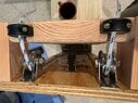
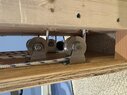
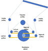
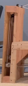
Building a DIY kayak simulator training machine. A rope is tied to each end of a broomstick and runs around a resistance wheel, guided by a system of seven pulleys .

The machine works exactly as intended. But I feel there is too much drag. Trying to see how I can reduce the drag,in the system.

Transfer pulley is a 4" clothesline pulley

Remaining pulleys are 1 1/2" stainless block mounted pulleys.

Rope is 1/4" double braided marine rope.

Possibles -- replace stainless pulleys with nylon or ceramic? Replace woven rope with wire rope?


Thanks -- Bob

ergometer_full.jpg
 

Attachments

  • ergometer.jpg
    ergometer.jpg
    25.5 KB · Views: 69
  • pulley_retail.jpg
    pulley_retail.jpg
    12.3 KB · Views: 61
Last edited by a moderator:
  • Like
Likes   Reactions: berkeman
Engineering news on Phys.org
  • Larger diameter pulleys?
  • Less "wrap" around the pulleys? (It looks like #1 right and left pulleys have about 250 degrees on them, any reason that can't be 70 degrees?)
  • Are the pulleys fixed, or free to pivot? If you can fix them, even somewhat, that may help.
  • Double-braided marine rope might have some inherent twist.

I am spitballing. I am not a mech eng (but I am a sailor, so familiar with friction in running lines ).
 
Last edited:
  • Like
Likes   Reactions: Nik_2213
DaveC426913 said:
  • Larger diameter pulleys?
  • Less "wrap" around the pulleys? (It looks like #1 right and left pulleys have about 250 degrees on them, any reason that can't be 70 degrees?)
  • Are the pulleys fixed, or free to pivot? If you can fix them, even somewhat, that may help.
  • Double-braided marine rope might have some inherent twist.

I am spitballing. I am not a mech eng (but I am a sailor, so familiar with friction in running lines ).
Don’t be misled by the sketch; it’s a 3D system so 2D doesn’t do it justice.

All pulleys are apx 90 degrees except the transfer pulley is apx 180
 

Attachments

  • IMG_1389.jpeg
    IMG_1389.jpeg
    82.4 KB · Views: 66
  • IMG_1390.jpeg
    IMG_1390.jpeg
    70.6 KB · Views: 60
  • ergometer_flow.jpg
    ergometer_flow.jpg
    23.8 KB · Views: 76
Last edited:
Are those lines run through raw holes in the lumber? You could be picking up a lot of friction there.

I do think a thinner cable would reduce friction. There are high performance lines that hold the same force as 1/4", but are much thinner. And it's an easy fix,
 
Yes, raw wood holes, but 1-1/4" diameter so there shouldn't be muchfriction there; just there to keep the rope from walking off the resistance wheel.

The only planned-in friction is the stainless fairlead that directs the rope to the intake pulley
 
I'm not able to tell from the drawings -- does the resistance wheel change directions with left/right rowing, or does it keep rotating in one direction like a typical rowing machine?
 
Good question. Resistance wheel goes in the same direction both sides. Resistance wheel swiped from a Nordic Track ski machine; I had to reverse on of the rollers.
 
Last edited:
A kayak is pushed forwards by the paddler's foot, on the opposite side to the active paddle stroke. The power comes from body-trunk torque and glutes, not from the arms. The arms are more like struts or links, while one wrist only controls the blade angle. The body rocks backwards and forwards with each stroke, that also lengthens the stroke in the water.

Your feet and seat are co-linear, so do not prevent sideways rolling movement. A kayak paddler will have knees bent and apart, braced against the upper hull. You also need sides to the seat. That will balance side forces when paddling.

You will hurt your back with your arrangement because your waist-trunk will be locked, while your arm muscles will be doing the work. That is the opposite of paddling a kayak.
 
  • Informative
Likes   Reactions: berkeman and DaveC426913
Thanks for the feedback. Well aware of the opposing foot-to-arm force in the paddle stroke. . . a buddy of mine had to cut back on his paddling cos he has a bad knee! ... as well as trunk rotation. Still fiddling with location of the foot rest . . . which is why it's secured with screws, not nails. As to the seat, a tractor seat on ebay was the best I could find.

FYI this is the device I'm using as a model

1723236787703.png
 
  • #10
My kayak hoist has 3 pulleys and 3/8" twisted rope. The pulleys are hardware store pulleys about 2" diameter. Angles of wrap of the pulleys are approximately 180, 110, and 70 degrees. I attached a spring scale and it needed 85 lbs to raise the kayak, and 35 lbs to lower it. The difference is friction.

I think that your largest source of friction is the small diameter pulleys, along with the rope diameter. I suggest changing to pulleys at least 3", or better yet 4", diameter with your 1/4" rope. The pulley material is not important as long as the bearings are at least Oilite or plastic.
 
  • #11
This surfski video shows how the paddler's arms and legs engage .

 
  • #12
jrmichler said:
My kayak hoist has 3 pulleys and 3/8" twisted rope. The pulleys are hardware store pulleys about 2" diameter. Angles of wrap of the pulleys are approximately 180, 110, and 70 degrees. I attached a spring scale and it needed 85 lbs to raise the kayak, and 35 lbs to lower it. The difference is friction.

I think that your largest source of friction is the small diameter pulleys, along with the rope diameter. I suggest changing to pulleys at least 3", or better yet 4", diameter with your 1/4" rope. The pulley material is not important as long as the bearings are at least Oilite or plastic.
Good to know. Not aware what my bearings are made of...
 
  • #13
bobthebuilder said:
The machine works exactly as intended. But I feel there is too much drag. Trying to see how I can reduce the drag,in the system.
I don't understand how friction causes too much drag when you add a resistance wheel. Can't you just reduce the resistance from the wheel?
 
  • Like
Likes   Reactions: gmax137
  • #14
I guess I want to be able to control the drag. That is, so the only source of rewsistance is from the resistance wheel
 
  • #15
In that case, those fairleads:

1723242210778.png


would be better as upright lead blocks, thus:


1723242697860.png


Never mind, youre just using them as straight guides. I thought they were going through a 90 degree turn, but they're not.
 
Last edited:
  • #16
While you're at it, you might want to replace that decaying old component between seat and paddle with a newer, hotter one. Lotta friction there! :oldbiggrin:
 
Last edited:
  • Haha
Likes   Reactions: bobthebuilder and gmax137
  • #17
bobthebuilder said:
This surfski video shows how the paddler's arms and legs engage .
I'm not seeing any leg motion. How can they contribute much work if the lower body is not moving? It's not like a scull with a moving seat...

berkeman said:
I'm not able to tell from the drawings -- does the resistance wheel change directions with left/right rowing, or does it keep rotating in one direction like a typical rowing machine?
bobthebuilder said:
Good question. Resistance wheel goes in the same direction both sides. Resistance wheel swiped from a Nordic Track ski machine; I had to reverse on of the rollers.
I'm not able to see from your drawings how the two rope inputs are able to drive the resistance wheel in the same direction. Do you use two bicycle freewheel gearsets to accomplish this?
 
  • #18
In the video you can see the knees go up and down as the paddler drives his foot on the paddle stroke side.

The resistance wheel is from an old Nordic Track. As designed the rollers push the wheel on the forward slide and are idle on the back step. Reversing the roller on one side allows both paddle strikes to push the wheel in the same direction.
 
  • #19
bobthebuilder said:
Replace woven rope with wire rope?
I vote for that simple solution, besides reducing the diameter to the minimum acceptable for the forces at play.
Consider that a good portion of the drag force comes from simultaneously bending the rope at each pulley.
 
  • #20
How about even simpler? Two resistance wheels, and, you know... :wink:
 

Similar threads

  • · Replies 27 ·
Replies
27
Views
11K
  • · Replies 7 ·
Replies
7
Views
3K
  • · Replies 29 ·
Replies
29
Views
4K
Replies
2
Views
10K