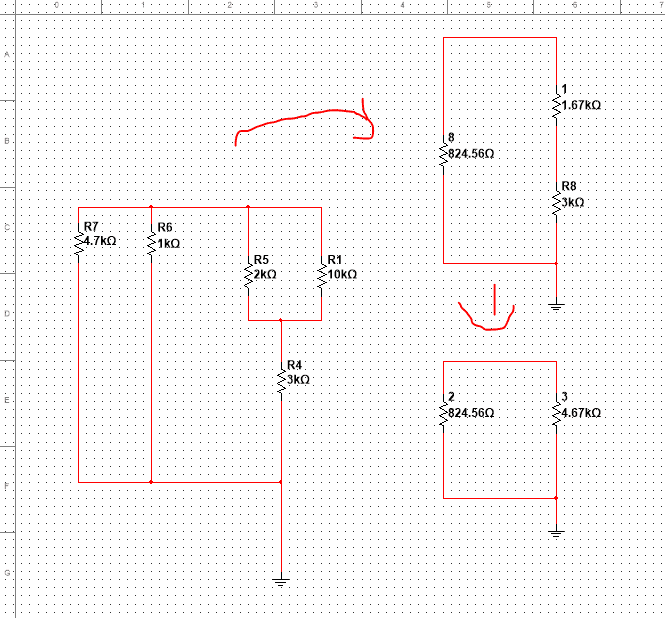
R_th wrong while applying series and parallel simple theory

14 replies · 3K views · last reply
Ohmslaw
Messages
1
Reaction score
0
Summary:: Trying to find Rth but I do not get the same value as the one from the solution.

[moderator: moved from a technical forum. No template.]

I am trying to find Rth to solve this problem, however once I simplified it, I get a value of 700.745 Ω while in the solution, the answer is 1.161kΩ. How is that possible ? What goes in parallel and what goes in series ?

Thank you !
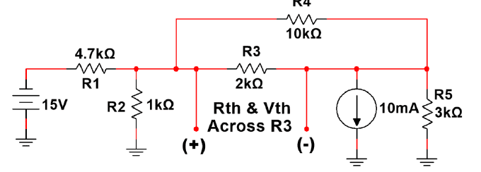
Circuit schematic with a 15V source, R1 4.7kΩ in series, R2 1kΩ to ground, R4 10kΩ across the top, R3 2kΩ between marked (+) and (-) terminals, a 10mA current source to ground, and R5 3kΩ to ground at right; labelled Rth & Vth across R3.

Circuit schematic of a resistor network with R1 10kΩ, R4 3kΩ, R5 2kΩ, R6 1kΩ and R7 4.7kΩ, plus a separate network of 1.67kΩ, 3kΩ, 824.56Ω and 4.67kΩ resistors, with red markup lines.
 
Last edited by a moderator:
1. This looks like a homework question. It ought to be posted in that forum.
2. Is your simplification from the perspective of R3?
When I calculate the resistive network from the perspective of R3 it works out to 1.161K
 
It looks like you almost had it. My recommendation would be to move that ground so it's easier to interpret. Let's say we move it to where the V- is and draw the old ground as wires connecting to each other?

I'm not solving it for you... just redrawing it in a different way :) Would this be okay for you?

Hand-drawn circuit redrawn with a new ground reference at the V minus terminal. Resistors R1, R2, R3, R4 and R5 are shown with the source and terminals labelled +, V and minus, with the earlier ground marked as old ground.
 
  • Like
Likes   Reactions: hutchphd, etotheipi, Asymptotic and 2 others
Ohmslaw said:
I get a value of 700.745 Ω

Based on your circuit diagram, it seems that you have found the equivalent resistance of the terminal (+) with respect to ground instead of the equivalent resistance of (+) with respect to (-).
 
  • Like
Likes   Reactions: hutchphd and Asymptotic
Assuming the circle with the arrow is an amperemeter: R5 is in parallel with it, so it doesn't do anything. You get three parallel resistors and then R1 and the voltage source as separate elements.
 
Asymptotic said:
When I calculate the resistive network from the perspective of R3 it works out to 1.161K
Including R3, right?
 
hutchphd said:
Asymptotic said:
1. This looks like a homework question. It ought to be posted in that forum.
2. Is your simplification from the perspective of R3?
When I calculate the resistive network from the perspective of R3 it works out to 1.161K
Including R3, right?

That answer will include R3. I think a few people have answered this question :)
 
The phrasing seems odd to me. "From the perspective of R3" would seem to exclude R3 from the Thevenin. Semantics...
 
I agree: It makes R3 sound like the load. I solved it just to be sure.
 
hutchphd said:
The phrasing seems odd to me. "From the perspective of R3" would seem to exclude R3 from the Thevenin. Semantics...

Circuit schematic with a 15V source, R1 4.7kΩ, R2 1kΩ, R3 2kΩ, R4 10kΩ, R5 3kΩ and a 10mA current source, with Rth and Vth marked across R3 between the (+) and (-) terminals.


"Perspective" was the first word that came to mind (at least, to my mind) that conveyed the essence of "Rth across R3".

Perspective, in the sense of "the combination of me, and all those connected to me". By that definition, network resistance from the perspective of R1 is 700.75Ω, from R3 is 1160.81Ω, and from R5 is 1361.02Ω.
 
Which is why we draw schematics! Worth more than a thousand words. Thanks.