Representation of a threaded section

2 replies · 2K views · last reply
Amaelle
Messages
318
Reaction score
55
Homework Statement
look at the image
Relevant Equations
engineering drawing
Greetings!
I´m trying to solve the following exercice
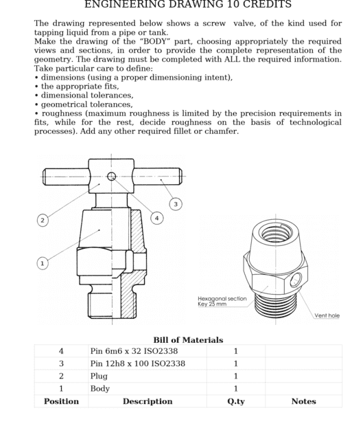
Engineering drawing of a screw valve with a sectioned side view showing a handle, body and plug, numbered callouts 1 to 4, and a 3D pictorial view of the body with a hexagonal section and vent hole, plus a bill of materials table.

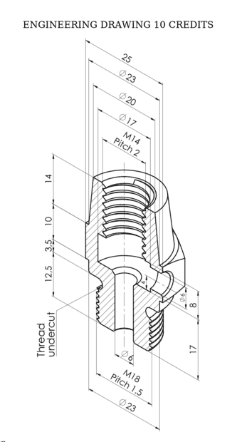
Isometric cross-section engineering drawing of a threaded fitting titled Engineering Drawing 10 credits, with dimensions 25, 23, 20, 17 (diameters), M14 pitch 2 internal thread, M18 pitch 1.5 external thread, bore 6, and dimensions 14, 10, 3.5, 12.5, 8, 17, plus a thread undercut callout.
I have done the following drawing for the cross section
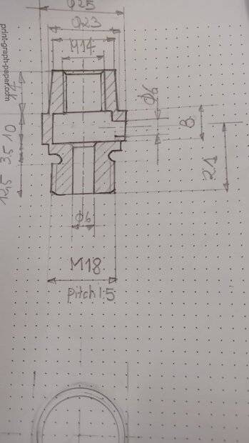
Hand-drawn sectional view of a stepped threaded fitting, dimensioned with M18 and M14 threads, pitch 1.5, and diameters including 25, 23, 6, 8 and 21 marked with leader lines.
and I want to know if I need to add a top view or any other additional view? (is the cross section enough)

thank you!
 
Just imagine that you have to build that body from a chunk of metal.
What dimensions would you need?
Is any of the dimensions shown in the isometric drawing not needed to be included in your side or elevation view?

I believe that I could do it using that single view, as long as the symbol for diameter is properly used where needed, and a note specifying one single lateral hole is added.
 
Lnewqban said:
Just imagine that you have to build that body from a chunk of metal.
What dimensions would you need?
Is any of the dimensions shown in the isometric drawing not needed to be included in your side or elevation view?

I believe that I could do it using that single view, as long as the symbol for diameter is properly used where needed, and a note specifying one single lateral hole is added.
thanks a million!