david03
- 2
- 0
- Homework Statement
- You have been given pedalling force data for 10 cyclists to analyse. Write a Matlab code to calculate the following for each cyclist:
Throughout the pedal stroke (i.e. additional columns of data):
• Resultant pedal force (FRESULTANT)
• Force tangential to the crank arm (crank arm length = 170 mm) (i.e. the effective pedal force, FEFFECTIVE)
Single values for the pedal stroke:
• Peak torque and angle of peak torque
• Positive and negative work done during the pedal stroke
• Mean power throughout the pedal stroke
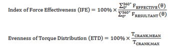
• Index of Force effectiveness (IFE)
• Evenness of torque distribution (ETD)
Part 2
Divide the cyclists into two groups based on their ETD values; a good group with ETD ≥ 25%; and a poor group with ETD < 25%. Perform statistical tests to determine if there is a difference between these two groups for each of the remaining six single value variables calculated above. Present the results for each of these six variables as bar charts (presenting the mean and standard deviation for each group)
Notes
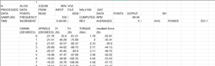
The cyclist data is in an excel spreadsheet that can be downloaded from Learn (data_cycle_10.xlsx). Each worksheet contains the data for one cyclist and the five columns to data are:
CRANK crank angle measured clockwise from top dead centre (i.e. vertical pointing upwards)
SPINDLE pedal spindle angle measured anti-clockwise from horizontal
Ft and Fn are the forces applied to the pedals tangential and normal to the pedal surface
TORQUE torque applied to turning the crank arm (TCRANK)
- Relevant Equations
- attached below as photos
%% part 1
clear all; close all; clc;
torq_crPK = zeros(10,1);
ang_tqPK = zeros(10,1);
ang_powPK = zeros(10,1);
torq_crDS = zeros(10,1);
torq_crUS = zeros(10,1);
WD = zeros(10,1);
WDpos = zeros(10,1);
WDneg = zeros(10,1);%% INPUT VARIABLES
for i=1:10 % cyclist number
% read in the cyclists data
if (i < 10)
data1=xlsread('21WSB302_matlab_report_data.xlsx',['cycle0' num2str(i)],'B10:F370'); % angle-torque data
else
data1=xlsread('21WSB302_matlab_report_data.xlsx',['cycle' num2str(i)],'B10:F370'); % angle-torque data
end
%% PART 1
ang_cr=data1(:,1); % crank angle
torq_cr=data1(:,5); % crank torque
% peak values (10)
[torq_crPK(i,1),]=max(torq_cr);
ang_tqPK(i,1)=ang_cr(i); % peak torque and angle where it occurs
ang_powPK(i,1)=ang_cr(i); % peak power and angle where it occurs
% averages (4&5)
[iDS]=find(ang_cr<=180);
torq_crDS(i,1)=mean(torq_cr(iDS)); % average downstroke torque
[iUS]=find(ang_cr>180);
torq_crUS(i,1)=mean(torq_cr(iUS)); % average upstroke torque
% work done total
WD(i,1)=trapz(deg2rad(ang_cr),torq_cr); % numerical integration of torque wrt angle (in radians)
% positive work done
% create a copy of torq_cr
% find all the negative torques in the copy
% reset the negative torques to zero
% apply trapz to this copy
torq_pos=torq_cr;
ineg=find(torq_cr<0);
torq_pos(ineg)=0;
WDpos(i,1)=trapz(deg2rad(ang_cr),torq_pos);
% negative work done
% create a second copy of torq_cr
% find all the positive torques in the second copy
% reset the positve torques to zero
% apply trapz to this second copy
torq_neg=torq_cr;
ipos=find(torq_cr>=0);
torq_neg(ipos)=0;
WDneg(i,1)=trapz(deg2rad(ang_cr),torq_neg);
end
%% WRITE DATA
headings={'sub','torqPK','ang_tqPK','torqDS','torqUS','powPK','ang_powPK','powMN','workNET','workPOS','workNEG'};
subs=[1:10]';
data_out=[subs torq_crPK ang_tqPK torq_crDS torq_crUS ang_powPK WD WDpos WDneg]; % create a single matrix with all the data first
xlswrite('21WSB302_matlab_report_data.xlsx',headings,'results','I10');
xlswrite('21WSB302_matlab_report_data.xlsx',data_out,'results','I11');
Attachments
Last edited: