revird163
- 1
- 0
Poster has been reminded to post schoolwork in the HH forums and use the HH Template in the future
I have been been trying to search forums and figure out the following question that I just cannot seem to get my head around!
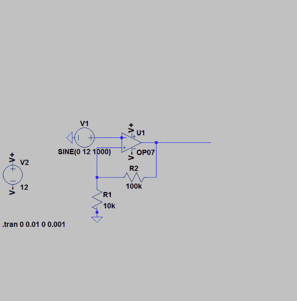
Design a Schmidt comparator circuit based on an OP07 operational amplifier with the following characteristics: Power supply Voltages: +/- 12V Switching thresholds +1V, -1V
I have been trying to figure out the voltage saturation and then using this to find the resistor values for the schmidt trigger. I cannot work out what the voltage saturation is and how to calculate it at all.
Any help would be appreciated, I am really not the best at electronics!
The following is the circuit I am trying to use modeled on LTSpice:
Design a Schmidt comparator circuit based on an OP07 operational amplifier with the following characteristics: Power supply Voltages: +/- 12V Switching thresholds +1V, -1V
I have been trying to figure out the voltage saturation and then using this to find the resistor values for the schmidt trigger. I cannot work out what the voltage saturation is and how to calculate it at all.
Any help would be appreciated, I am really not the best at electronics!
The following is the circuit I am trying to use modeled on LTSpice:
