Nick Amos
- 2
- 1
Hello everyone, this is my first post here so please excuse me if its in the wrong area.
I am looking for the tabular approach to solve a complex gear train based off the spur gear differential design. Attached is a photo of the differential.
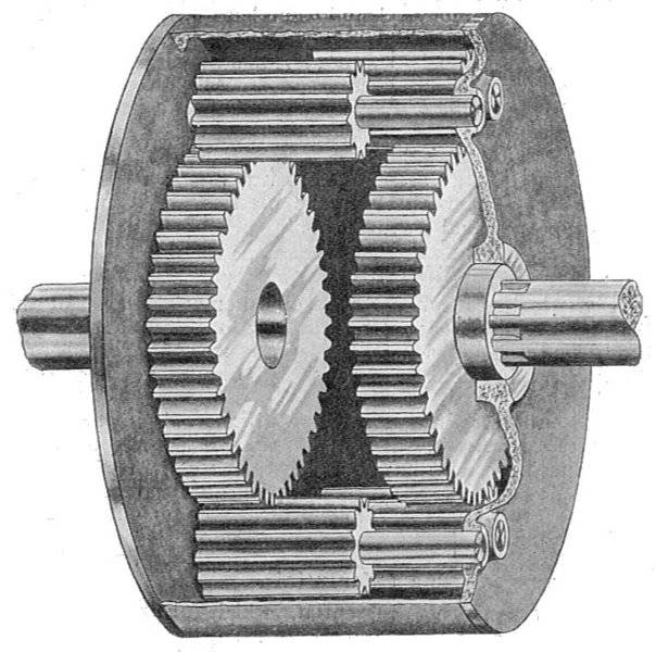
The requirements of the necessary differential will be:
Sun-Gear 1 as input,
Carrier or Sun-Gear 2/Annular gear as outputs. Only one output will be in motion at any given time.
The velocity of the outputs must be equal.
A condition of the differential in the above photo is that the carrier velocity ratio is an average of the velocity of the two sun gears. When applied to the above conditions, the outputs would not be equal. The annular gear output would be equal and opposite to the input, while the carrier output would be equal to 1/2 the input speed.
To achieve the equal output velocities, the ratios of either sun to planet set can be modified, as well as the ratio of planet to planet. I am a novice with tabular gear train solutions and am confused by which method to move forward with in order to solve this.
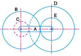
The first possible solution I thought would be in a modification to the tabular method used for Reverted epicyclic gear trains.
The second, was a modified version of the method used for compound epicyclic gear trains.
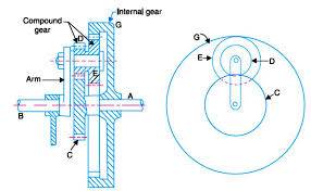
In order to modify the reverted design, the gears D and E would no longer be compound and the ratio of the two would be necessary in calculations. In the compound epicyclic case, the Annular gear would have external teeth and its rotational direction changed as well as Gears D and E not being compound.
Here is a simple photo showing the method permitting modified ratios. Sun Gear A would be the input. The outputs would be either Carrier H or Annular GearD/Sun Gear 2.
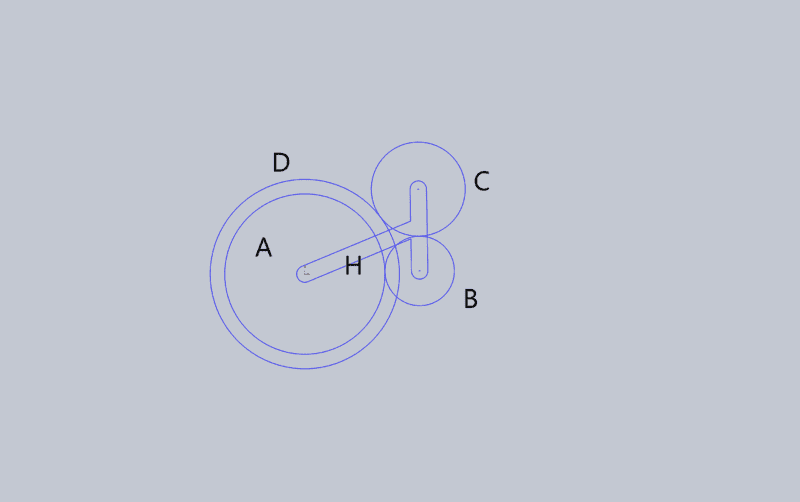
If the Annular gear is the Output, Gears B and C act as Idlers and the ratio of input to output is that of A:D, properly expressed: NA/NB X NB/NC X NC/ND or simply NA/ND
This is where I need help. When tabulated, what does this method look like? I've come up with what I thought was the right table, but when comparing the equations for gears b and c to those of similar complex systems It seems I'm missing some things. Once I have the table I should be able to use the formulas and set the ratios between gears by using my operational parameter that the velocity of H must be equal to that of NA/ND right?
Here is what I believe is the right table representing this method of motion.
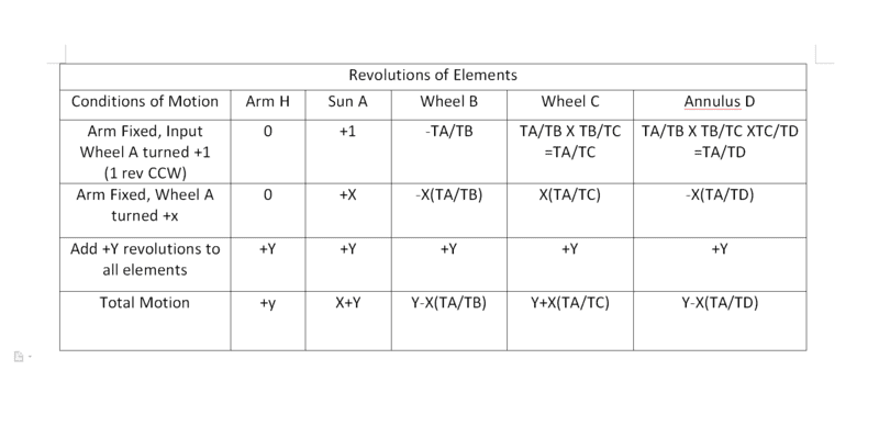
Any help or direction is greatly appreciated!
I am looking for the tabular approach to solve a complex gear train based off the spur gear differential design. Attached is a photo of the differential.
The requirements of the necessary differential will be:
Sun-Gear 1 as input,
Carrier or Sun-Gear 2/Annular gear as outputs. Only one output will be in motion at any given time.
The velocity of the outputs must be equal.
A condition of the differential in the above photo is that the carrier velocity ratio is an average of the velocity of the two sun gears. When applied to the above conditions, the outputs would not be equal. The annular gear output would be equal and opposite to the input, while the carrier output would be equal to 1/2 the input speed.
To achieve the equal output velocities, the ratios of either sun to planet set can be modified, as well as the ratio of planet to planet. I am a novice with tabular gear train solutions and am confused by which method to move forward with in order to solve this.
The first possible solution I thought would be in a modification to the tabular method used for Reverted epicyclic gear trains.
The second, was a modified version of the method used for compound epicyclic gear trains.
In order to modify the reverted design, the gears D and E would no longer be compound and the ratio of the two would be necessary in calculations. In the compound epicyclic case, the Annular gear would have external teeth and its rotational direction changed as well as Gears D and E not being compound.
Here is a simple photo showing the method permitting modified ratios. Sun Gear A would be the input. The outputs would be either Carrier H or Annular GearD/Sun Gear 2.
If the Annular gear is the Output, Gears B and C act as Idlers and the ratio of input to output is that of A:D, properly expressed: NA/NB X NB/NC X NC/ND or simply NA/ND
This is where I need help. When tabulated, what does this method look like? I've come up with what I thought was the right table, but when comparing the equations for gears b and c to those of similar complex systems It seems I'm missing some things. Once I have the table I should be able to use the formulas and set the ratios between gears by using my operational parameter that the velocity of H must be equal to that of NA/ND right?
Here is what I believe is the right table representing this method of motion.
Any help or direction is greatly appreciated!
Attachments


