fahraynk
- 185
- 5
Hi, I am a bit confused. So I have a shaft with a step on both sides so it gets really large in the middle. I am trying to model torsion on the rotor of a BLDC motor with FEA (or by hand calculations).
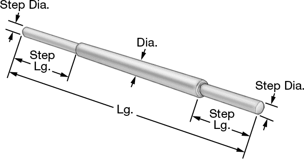 If I apply a moment on the sides and fix the faces at the end of the shaft I get 1 result. If I apply a moment on the end face and fix the other end face I get another result.
If I run a motor on max power and hold the end of the shaft so it does not move... Where should I apply the moment in my calculation, on the end of the shaft I am holding or on the side face of the shaft where the motor is creating the power? How do you express this difference in a torsion calculation? In a torsion calculation there is nowhere to put the face the torque is applied to, but in a finite element analysis the results come out differently if I apply the torque to different faces of the object.
If I run a motor on max power and hold the end of the shaft so it does not move... Where should I apply the moment in my calculation, on the end of the shaft I am holding or on the side face of the shaft where the motor is creating the power? How do you express this difference in a torsion calculation? In a torsion calculation there is nowhere to put the face the torque is applied to, but in a finite element analysis the results come out differently if I apply the torque to different faces of the object.