Discussion Overview
The discussion revolves around troubleshooting a 30 kV power supply that is not producing the expected discharge between electrodes. Participants explore potential issues related to the oscilloscope's measurement capabilities, the configuration of the power supply, and the discharge setup itself. The conversation includes technical details about the equipment used and the conditions under which the discharge is expected to occur.
Discussion Character
- Technical explanation
- Debate/contested
- Experimental/applied
Main Points Raised
- One participant notes that the oscilloscope's input impedance may overload the 30 kV supply, suggesting the use of a high voltage probe.
- Another participant questions whether a discharge occurs without the oscilloscope or probe, indicating a need to test this condition.
- Concerns are raised about the potential for the probe to overload the power supply, with some participants suggesting that either the probe, the power supply, or the discharge tube could be faulty.
- Participants propose a systematic approach to troubleshooting, including testing components independently and checking calibration.
- One participant mentions a 1 k ohm resistor in the circuit, speculating on its role in managing leakage currents and preventing insulation breakdown.
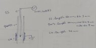
- There is a discussion about the dimensions of the discharge tube, with some participants asserting that it is unlikely to be the source of the problem.
Areas of Agreement / Disagreement
Participants express multiple competing views regarding the source of the problem, with no consensus reached on whether the issue lies with the power supply, the probe, or the discharge tube. The discussion remains unresolved as participants explore different hypotheses and troubleshooting steps.
Contextual Notes
Participants mention the need for a data sheet for the power supply and probe, indicating that specific technical details may be necessary for further analysis. There is also uncertainty about the circuit schematic and how components are interconnected.
Who May Find This Useful
This discussion may be useful for individuals working with high voltage power supplies, oscilloscope measurements, and discharge experiments, particularly in experimental physics or engineering contexts.