Understanding Engineering Drawings: Deciphering Front and Bottom Views

  • Thread starter Thread starter hunter300
  • Start date Start date
  • Tags Tags
    Engineering
Join the discussion
Registration is free. Start your own thread to ask a follow-up.
6 replies · 3K views · last reply
hunter300
Messages
3
Reaction score
0
Hi,

Could somebody help me with this please...its probably really simple but i am just so confused...
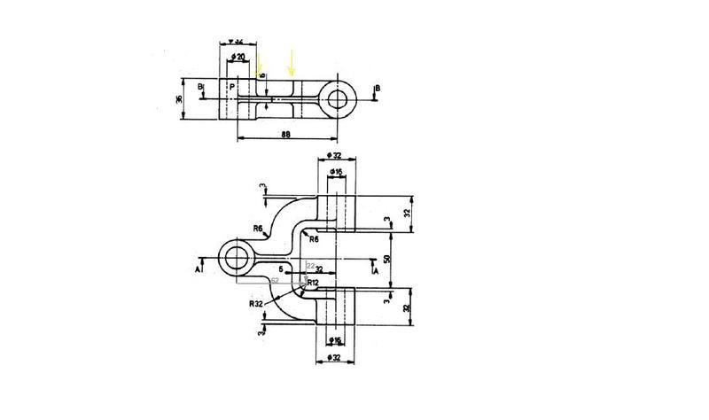
Orthographic engineering drawing of a bracket with a top view showing a 88 mm length and 36 mm width with an end bore, and a lower view with R6, R12 and R32 radii, bores d15 and d20, and a 50 dimension.


the bottom view shows the plan view and top shows front view wat i don't get is that why does the front view have the lines that i have indicated with yellow arrows...
and secondly how would u decide whether the component is circular tube or non-circular i.e flat from the front view...

Please help me

Thank you in advance
 
Physics news on Phys.org
The left yellow line is the bottom tangent of the circular feature on the left hand side of the bottom view. The right yellow line is the left edge of the "U" shape feature.

If you ever wonder where a line comes from, simply draw a construction line perpendicular to the view line that separates the two views and it will intersect the feature that is responsible for the line.
 
Attachments
  • Engineering drawing of a bracket with a top view above and a front view below, joined by a dashed view line; dimensions include 88, 36, 50, 32, R6, R12, R32, phi 20, phi 16, phi 32 and sections marked A and B.
    Untitled.jpg
    25.5 KB · Views: 460
Last edited:
FredGarvin said:
The left yellow line is the bottom tangent of the circular feature on the left hand side of the bottom view. The right yellow line is the left edge of the "U" shape feature.

If you ever wonder where a line comes from, simply draw a construction line perpendicular to the view line that separates the two views and it will intersect the feature that is responsible for the line.

Thanx a lot for your help...i understand which feature is responsible for those lines but wat i don't get is that why are they are drawn the way they are...

I am strugling with wat it looks like interm of physical appearance...
 
A circle on its side looks like a rectangle. It is complicated because of the radii that are helping to eliminate the sharp corners.
 
I threw together a quick 3D for you. Hope it helps.
 
Attachments
  • Two shaded 3D renderings of the same mechanical bracket casting, shown from different angles against a dark background, with three cylindrical bosses each having a through-hole.
    crap.jpg
    12.6 KB · Views: 468
FredGarvin said:
I threw together a quick 3D for you. Hope it helps.

Waooooooooooooo... thanks ever so much that helps a lot except i have handed in my drawings this morning...

But thanks a lot for your helpppppppppppp...seriously

does this forum have like a rep system...coz i would love to give rep u

Ur AWESOME