What is the final angular displacement of a disk hit by two masses?

AI Thread Summary
The discussion focuses on calculating the final angular displacement of a disk after being hit by two masses using conservation laws. The conservation of linear momentum is applied to determine the center of mass velocity, while angular momentum conservation is used to find the angular velocity of the system post-collision. The impulse theorem is also referenced to calculate the impulse imparted by the rod. A detailed analysis of the angular displacement is provided, leading to the conclusion that the center of mass does not coincide with the disk's center, affecting the angular momentum calculations. The final equations derived confirm the relationship between the system's angular velocity and its displacement.
lorenz0
Messages
151
Reaction score
28
Homework Statement
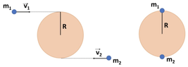
A disk of mass ##m=10kg## e raggio ##R=0.5 m## is initially at rest on a horizontal plane without friction. Two point masses ##m_1=5kg## and ##m_2=1kg## move with speed ##v_1=2m/s## and ##v_2=4m/s## the first from left to right and the second from right to left. At a certain istant ##m_1## and ##m_2## hit the disk in a completely inelastic collision.
Find: 1) Velocity of the center of mass after the collision; 2) Angular velocity of the disk after the collision; 3) If the disk had a rod passing through its center of mass and perpendicular to the the disk find its angular velocity after the collision and the impulse given by the rod in the collision; 4) If now the rod where to apply a braking torque ##\tau=-0.2 N\cdot m## to the disk, after how many turns would the disk (with the two masses) stop?
Relevant Equations
##\vec{L}=\vec{r}\times\vec{p}=I\vec{\omega}, \omega_f^2=\omega_i^2+2\alpha\Delta\theta##
1) By conservation of linear momentum: ##m_1 v_1-m_2v_2=(m+m_1+m_2)v_{cm}\Rightarrow v_{cm}=\frac{m_1}{m+m_1+m_2}v_1-\frac{m_2}{m+m_1+m_2}v_2=\frac{3}{8}\frac{m}{s}##;

2) By conservation of angular momentum: ##-Rm_1v_1-Rm_2v_2=I_{total}\omega=(I_{disk}+m_1R^2+m_2R^2)\omega## so
##-(m_1v_1+m_2v_2)R=(\frac{1}{2}mR^2+m_1R^2+m_2R^2)\omega\Rightarrow\omega=-\frac{m_1v_1+m_2v_2}{\frac{m}{2}+m_1+m_2}=-\frac{14}{11}\frac{rad}{s}##;

3) To find the impulse given by the rod we can use the impulse theorem so ##I=(m+m_1+m_2)v_{cm}=16\cdot\frac{3}{8}\frac{kg\cdot m}{s}=6 \frac{kg\cdot m}{s}##. Now, to find the angular velocity in this case I would do the same analysis as in (2) and say the angular velocity is thus the same but I am not sure so I would appreciate a comment about how to think about this case.

4) ##\omega_f^2=\omega_i^2+2\alpha\Delta\theta## which in our case gives ##0=\omega_i^2-2\frac{|\tau|}{I_{tot}}\Delta\theta\Rightarrow\Delta\theta=\frac{I_{tot}\omega_i^2}{2|\tau|}\omega_i^2=\frac{(\frac{1}{2})mR^2+m_1R^2+m_2R^2)\omega_i^2}{2|\tau|}\omega_i^2=\frac{(5+5+1)(\frac{1}{2})^2}{2\frac{1}{5}}(\frac{14}{11})^2 rad=\frac{245}{22} rad## so the number of turns is ##n_{turns}=\frac{\frac{245}{22}}{2\pi}=\frac{245}{44\pi}##.
 

Attachments

  • disk_masses.png
    disk_masses.png
    10.9 KB · Views: 174
Last edited:
Physics news on Phys.org
In part 2, you found the initial angular momentum of the disc+masses about a fixed point on the line through the disc's centre and parallel to the initial motions. E.g. about the point where the disc's centre started.
You then equated this to an angular momentum of the combined system after the collisions, about that point. But does that give you the rotation rate of the disc about its centre? What are the contributions to that angular momentum?
 
haruspex said:
In part 2, you found the initial angular momentum of the disc+masses about a fixed point on the line through the disc's centre and parallel to the initial motions. E.g. about the point where the disc's centre started.
You then equated this to an angular momentum of the combined system after the collisions, about that point. But does that give you the rotation rate of the disc about its centre? What are the contributions to that angular momentum?
Thanks for your interest in my question; I have been thinking about the problem and I think I have found the correct way to do part (2):

the center of mass of the system does not coincide with the center of mass of the disk and it is located at height ##0.625## from the lowest point of the disk i.e. ath height ##h=0.125 m## above the center of the disk. So, we have that ##L_{z_i}=-(R-h)m_1v_1-(R+h)m_2v_2## and ##L_{z_f}=(I_{disk_{cm}}+mh^2+m_1(R-h)^2+m_2(R+h)^2)\omega - (R+h)(m+m_1+m_2)v_{cm}## and from the conservation of angular momentum ##L_{z_i}=L_{z_f}## we can find ##\omega=\frac{(R+h)(m+m_1+m_2)v_{cm}-(R-h)m_1v_1-(R+h)m_2v_2}{m(\frac{1}{2}R^2+h^2)+m_1(R-h)^2+m_2(R+h)^2}##
and the answer I got in part (2) above is the answer to question 3, where the ##disk+m_1+m_2## system rotates around an axis through its center. Is this correct?
 
Last edited:
Your equation looks right, but in my experience it is generally unhelpful to find the CoM of such a system. Just work with an axis at the original mass centre position of the disc. The moments of the two point masses after collision are ##m_iR(R\omega\pm v)##.
 
Thread 'Minimum mass of a block'
Here we know that if block B is going to move up or just be at the verge of moving up ##Mg \sin \theta ## will act downwards and maximum static friction will act downwards ## \mu Mg \cos \theta ## Now what im confused by is how will we know " how quickly" block B reaches its maximum static friction value without any numbers, the suggested solution says that when block A is at its maximum extension, then block B will start to move up but with a certain set of values couldn't block A reach...
TL;DR Summary: Find Electric field due to charges between 2 parallel infinite planes using Gauss law at any point Here's the diagram. We have a uniform p (rho) density of charges between 2 infinite planes in the cartesian coordinates system. I used a cube of thickness a that spans from z=-a/2 to z=a/2 as a Gaussian surface, each side of the cube has area A. I know that the field depends only on z since there is translational invariance in x and y directions because the planes are...
Thread 'Calculation of Tensile Forces in Piston-Type Water-Lifting Devices at Elevated Locations'
Figure 1 Overall Structure Diagram Figure 2: Top view of the piston when it is cylindrical A circular opening is created at a height of 5 meters above the water surface. Inside this opening is a sleeve-type piston with a cross-sectional area of 1 square meter. The piston is pulled to the right at a constant speed. The pulling force is(Figure 2): F = ρshg = 1000 × 1 × 5 × 10 = 50,000 N. Figure 3: Modifying the structure to incorporate a fixed internal piston When I modify the piston...
Back
Top