Homework Helper
Gold Member
- 4,201
- 2,394
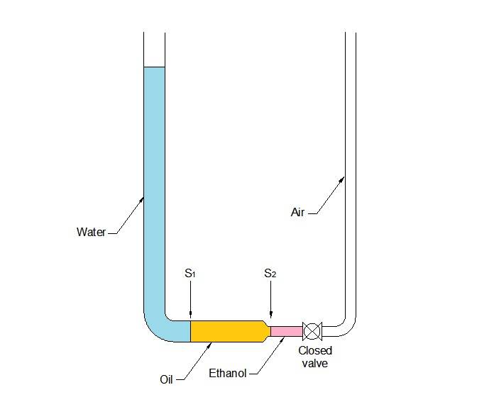
This diagram shows that you can have pressure on both sides of the volume of fluid you are analyzing.
Let's assume that your book represents only the volume of oil contained in the tube and transition.
As you can see, nothing is moving as represented; therefore, the value of static pressure in cross-sections S1 and S2 must be equal to the height pressure created by the column of water on the left leg.
Once the valve is opened, the pressure on S2 is the atmospheric pressure, which is transferred through the volume of ethanol.
The higher value of the static pressure acting on S1 will move oil and ethanol up through the horizontal and right vertical tube.
As the water level descends, the pressure on S1 gets smaller, while the pressure on S2 increases.
Naturally, the levels of the open surfaces inside the left and right vertical tubes, will tend to equalize.
When that state of balance is eventually reached (after some time of back-and-forth oscillations of the fluid inside the U-shaped tube), pressure on S1 will have a greater value than the pressure on S2 due to the height difference between both sections.
Let's assume that your book represents only the volume of oil contained in the tube and transition.
As you can see, nothing is moving as represented; therefore, the value of static pressure in cross-sections S1 and S2 must be equal to the height pressure created by the column of water on the left leg.
Once the valve is opened, the pressure on S2 is the atmospheric pressure, which is transferred through the volume of ethanol.
The higher value of the static pressure acting on S1 will move oil and ethanol up through the horizontal and right vertical tube.
As the water level descends, the pressure on S1 gets smaller, while the pressure on S2 increases.
Naturally, the levels of the open surfaces inside the left and right vertical tubes, will tend to equalize.
When that state of balance is eventually reached (after some time of back-and-forth oscillations of the fluid inside the U-shaped tube), pressure on S1 will have a greater value than the pressure on S2 due to the height difference between both sections.