Silvester
- 2
- 0
- TL;DR
- Determine the spacing between metal sheet and dielectric radome to achieve best RCS for various incident and reflection angle.
I'm working on a project about designing a radome for a reflector/scattering object like RIS or reflectarray. I run simulations on HFSS. For simplicity and the purpose of seeking regularity, i start with a dielectric radome(with relative permittivity = 3) and copper sheet.
Suppose that (1)large incident and reflection angle extends the length of propagation, and (2) higher RCS comes from the constructive interference. this problem should be easy to conquer after some simulations are done.
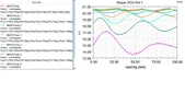
it turns out that as the incident angle increases, the spacing needed to have maximum RCS also increases, and peak or minimum RCS repeats with the period of half-wavelength/cos(theta) , corresponding to the wavelength of oblique angle.
but i can't figure out what spacing would the first peak show up.
i doubted it's about phase (constructive/destructive interference), but HFSS incident plane wave does not allow user to see the phase. i have written a MATLAB script to calculate the phase using transmission line analogy, the calculated phase does not match the HFSS result.
Suppose that (1)large incident and reflection angle extends the length of propagation, and (2) higher RCS comes from the constructive interference. this problem should be easy to conquer after some simulations are done.
it turns out that as the incident angle increases, the spacing needed to have maximum RCS also increases, and peak or minimum RCS repeats with the period of half-wavelength/cos(theta) , corresponding to the wavelength of oblique angle.
but i can't figure out what spacing would the first peak show up.
i doubted it's about phase (constructive/destructive interference), but HFSS incident plane wave does not allow user to see the phase. i have written a MATLAB script to calculate the phase using transmission line analogy, the calculated phase does not match the HFSS result.