Stability of different X-Frame Spreader Beam geometries

  • Level: Undergrad 
  • Thread starter Thread starter gen x
  • Start date Start date
Join the discussion
Registration is free. Ask a follow-up in this thread, or start your own.
4 replies · 1K views
gen x
Messages
176
Reaction score
8
How I can prove with physics that X-Frame Spreader Beam with 4 chains that goes to hook is more stable(less prone to CoG mismatch) then X-Frame Spreader Beam that have fixed hook at center of beam. Does in both case CoG of the load pass through steel cable from cran?

kryss-spridare-med-kattingar.fa8f08a9.webp
images.webp
 
Physics news on Phys.org
gen x said:
Does in both case CoG of the load pass through steel cable from cran?
The crane cable above the hook will be vertical, with the CoG of the spreader and load being below, on the cable axis.

The stability of the system will be highly influenced by the load supported by the spreader beam, and by deformation of the virtual, close to a parallelogram, that forms below the spreader beam. Many crane accidents involve failure of one of the slings that hang below the spreader beam, as the beam tilts and transfers the full load to one side. Each of the corner chains needs to be rated for the full load.

The most typical failure occurs when, for example, an excavator is being unloaded from a vessel onto the wharf, or is being lowered down a vertical shaft. In those situations, the length of the four chains is restricted by the height of the crane jib. The most unstable case is your example, when the crane hook is at the centre of the spreader beam.

Rather than 3D, start by analysing the 2D situation, with the slings and load included.
 
A lifting beam has the hook on the top of the beam. The beam must be able to handle the bending moment at the lift point, and at all the applied load points.

A spreader bar is supported at two points from one crane hook. The load is suspended from those same two points. The spreader bar is in compression, without bending moment.

Your design appears to employ RHS which is good in compression, but may be insufficient to handle the moment as a beam. That is especially true where the hook attaches to the centre of the 'X' beams.

You have no bracing to keep the 'X' square at the centre. That may focus high forces onto the welded structure at the lifting 'hub'.

Your use of four points of support is structurally unbalanced, in that the length of all lines and chains must remain identical, or the 'X' will be pulled out of plane with high moments being focussed on the hub. Spreader bars are usually kept independent to avoid that problem.

What you have designed is not a lifting beam or a spreader bar, it is a lifting frame. It has either insufficient structure, or insufficient freedom of movement at the central hub connections.

When two people lift an object, the one who lifts highest carries the least load, the lower lifter must carry the greater part of the load. When climbing steps or stairs, the strongest lifter must be on the lower step, or the load must remain level. That is also true of lifting beams or spreader bars, that do not remain level.

A spreader bar needs to remain level, or to be rated above the total load. In this two crane lift, the load was rapidly transferred to the crane that lowered the load first (or fastest). Both the tilt of the spreader and the lowest crane combined to break one quarter of the sling. That is one reason why a 5:1 safety factor must be used for rigging.
 
Baluncore said:
The crane cable above the hook will be vertical, with the CoG of the spreader and load being below, on the cable axis.

The stability of the system will be highly influenced by the load supported by the spreader beam, and by deformation of the virtual, close to a parallelogram, that forms below the spreader beam. Many crane accidents involve failure of one of the slings that hang below the spreader beam, as the beam tilts and transfers the full load to one side. Each of the corner chains needs to be rated for the full load.

The most typical failure occurs when, for example, an excavator is being unloaded from a vessel onto the wharf, or is being lowered down a vertical shaft. In those situations, the length of the four chains is restricted by the height of the crane jib. The most unstable case is your example, when the crane hook is at the centre of the spreader beam.

Rather than 3D, start by analysing the 2D situation, with the slings and load included.
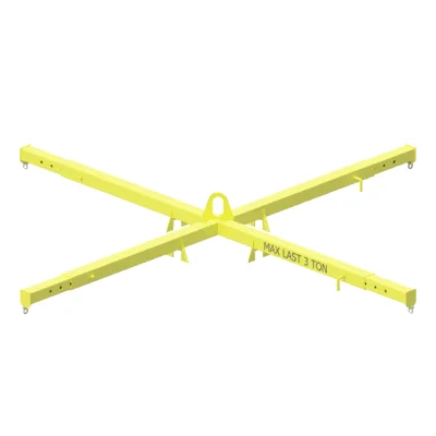
If you try lift weights with beam at my second photo, you must put CoG of weight 100% under the hook, otherwise beam will tilt, it is very sensitive and easy to make a accident.
I find better stability is when hook connection is above beam.
 
gen x said:
I find better stability is when hook connection is above beam.
That is true, but as I mentioned in my previous post, the 'X' is over-constrained, and so has too many disadvantages. Something must give.

Where the slings descend from the spreader bar above, they may attach above or below the CoG of the load. It is often the case with railway locomotives, or track-based earthmoving equipment, that the CoG of that load will be above the sling attachment points. That is an unstable configuration that may spontaneously invert the load, independent of the use of a lifting beam, or a spreader bar.

Where there is a lack of headroom, there may be insufficient space to allow the use of a spreader bar. A lifting beam, with a centre attachment point, would then need to be used.