50Hz and 60Hz supply neutral line question

AI Thread Summary
Mixing 50Hz and 60Hz supplies on a common neutral line is generally acceptable if the systems are properly designed. The inverter output at 60Hz can be connected to transformers referenced to the 50Hz supply, but care must be taken to avoid phase mismatches that could lead to excessive current draw. A variable frequency drive (VFD) can effectively manage the output, allowing for the production of regulated voltages at the desired frequency. Protective earths and neutrals should be interconnected, but no direct connections should be made between PE and N outside of the meter box. Using a VFD eliminates the need for transformers, simplifying the setup for resistive loads like heating machines.
petefa
Messages
3
Reaction score
1
TL;DR Summary
inverter and transformers
Hi,

I have a question, I think the answer is no you can't do it, but I want to know why.

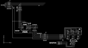
First mains supply - 3phase N + E (50hz)
Connected to this first supply is an inverter that gives out a 3 phase 415vac @60hz (no neutral) second supply.
The 60hz inverter output feeds 3 independent tapped transformers connected to the neutral of the first supply (50hz).

What would happen with one end of these transformer winding connected to second supply (60hz) with the other end of the transformer winding connect to the 50hz first supply neutral?Thanks
Pete
 
Engineering news on Phys.org
You blow all of the fuses and/or shut the inverter down. You can't connect AC power distribution if the frequencies don't match exactly. Although I might be misunderstanding you circuit. Always draw a schematic (and show it to us for the best answers). I think you'll see a transformer winding at 60Hz in parallel with a transformer winding driven at 50Hz, which means the voltages will be out of phase and draw lots of current.
 
  • Like
Likes petefa
@petefa , what specifically are you trying to accomplish? There may be a non-dangerous way to accomplish it.
 
Hi,
Thank you all for getting back to me.
This is what is being proposed.
 

Attachments

  • inverter.PNG
    inverter.PNG
    9.6 KB · Views: 205
The N and PE input are common to the entire system.
3PH+N+PE 50 Hz feeds a VFD that produces 415 V 3PH 60 Hz.
The 3PH output at 60 Hz drives the taps on three separate auto transformers, that are referenced to the common N. The three transformers provide the 3PH 60Hz output.

I see no immediate problem.
 
  • Like
Likes DaveE and sophiecentaur
DaveE said:
You can't connect AC power distribution if the frequencies don't match exactly.
It all depends what you stick in between them. A DC link is not uncommon where phases of the systems each end can't be relied on so a change of frequency is not out of the question, albeit possibly a bit more complicated.
petefa said:
Hi,
Thank you all for getting back to me.
This is what is being proposed.
From what I can see the circuit look OK but the resolution is too low to be sure.
However, t he bit that counts is in that box on the left. It could have a label "In here, a miracle occurs" or it could be a sophisticated switch mode inverter. There's no reason why the appropriate sides of the three 60Hz phases shouldn't be connected to Earth or a common conductor called Neutral and give a 60Hz 3phase output. That neutral can happily be connected to the Earth / Neutral of the incoming Power supply. Why not? Just don't try to connect any two of the other six terminals together!
 
No. I mean what is your application? I do not mean what is your solution.

Is there a 60 Hz device you want to use in a 50 Hz country? If yes, then please provide some details. What kind of device? How much power?
 
sophiecentaur said:
It all depends what you stick in between them.
LOL, OK, the less common interpretation of connected. Yup, you can put stuff between AC sources.
 
anorlunda said:
No. I mean what is your application? I do not mean what is your solution.

Is there a 60 Hz device you want to use in a 50 Hz country? If yes, then please provide some details. What kind of device? How much power?
Hi,
It's a UK testing supply to connect 10.5kw 208v 60hz water heating machines to. it's mainly resistive, (heaters) with a control circuit and control solenoids. Switched mode PSU, all components rated 50-60hz.

I wanted to know if you could mix the 50hz and 60hz supplies on the neutral line, as it's an inverter suppling the second supply.

Could there be interference as the inverter output isn't a true sine wave?
I think we will need a sine former or a reactor.
 
  • #10
petefa said:
I wanted to know if you could mix the 50hz and 60hz supplies on the neutral line, as it's an inverter suppling the second supply.
There is no problem having a common neutral for the 50 Hz and 60 Hz parts.
All protective Earth's are connected together. All neutrals are connected together. You make no connection between PE and N, that is done in the meter box.
You do not need the three transformers if you use a 3PH Variable Frequency Drive as the inverter. The VFD will have a neutral output terminal, and you can program the VFD to produce 208 volt at 60 Hz, or anything else in that ballpark you might want. With a resistive load the VFD will produce three sinewaves with regulated voltages, largely independent of the input.
 
  • Like
  • Informative
Likes berkeman and petefa
Back
Top