Analyzing Bridge Circuit w/ Loop Currents

  • Thread starter Thread starter guyvsdcsniper
  • Start date Start date
  • Tags Tags
    Resistors
AI Thread Summary
The discussion focuses on using the Loop Current Method to analyze a bridge circuit, specifically addressing difficulties in deriving equations for Loop B and C compared to the textbook. The user successfully applies the method to Loop A but encounters discrepancies in Loop B, particularly with voltage drop polarities and current directions at resistors. There is confusion regarding the signs assigned to the current terms, especially for resistor R2, and the need for consistency in sign conventions for currents in the same loop. The user realizes that the direction of the loop affects the voltage drop polarities, suggesting that the method requires careful attention to the assigned polarities based on the loop's traversal direction. Ultimately, understanding the relationship between loop direction and voltage polarity is crucial for accurate analysis using the Loop Current Method.
guyvsdcsniper
Messages
264
Reaction score
37
Homework Statement
Use the loop current method on bridge circuit to generate 3 loop equations
Relevant Equations
Kirchoff's law
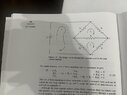
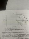
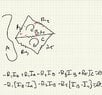
Attached is the example I am working out of a textbook that involves using the Loop Current Method on a bridge circuit. In the pictures attached I am following section 1.6.2 which produces loop equations (1.24) for figure 1.9. Figure 1.7 provides the direction of current.

I am having trouble producing the same result as the book I am using for Loop B and C.

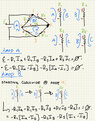
Following Loop A, we travel up the EMF,
##\varepsilon##, and then we reach ##R_1##. At this resistor, ##I_a## travels down the resistor and ##I_b## travels up it. Likewise, at ##R_3## ##I_a## travels down the resistor and ##I_c## travels up it. Traveling down the resistor leads to a drop in voltage which leads to a negative sign in associated with that voltage.

Following this logic, I receive the same equation for Loop A as seen in equation 1.24.

So now when evaluating Loop B, I will begin at Node 4. Again, at ##R_1## ##I_a## travels down the resistor and ##I_b## travels up it. This produces ##R_1I_b-R_1I_a##. Next we go down resistor ##R_2## and get ##-R_2I_b##. Finally we have resistor ##R_5##. ##I_b## travels up and ##I_c## travels down this resistor, giving ##R_5I_b-R_5I_c##. Simplifying this and setting it equal to zero gives:

$$-R_1[I_a-I_b]-R_2I_b-R_5[I_c-I_b]=0$$.

So my logic works for Loop A but for Loop B, this logic produces the opposite of what the book gives for the resistors that contain a superposition of current.

Could someone help me understand how I am approaching this wrong?
 

Attachments

  • IMG_4459.JPG
    IMG_4459.JPG
    44.4 KB · Views: 130
  • IMG_4462.JPG
    IMG_4462.JPG
    44.4 KB · Views: 108
  • IMG_4463.JPG
    IMG_4463.JPG
    32.3 KB · Views: 115
Physics news on Phys.org
guyvsdcsniper said:
at ##R_1## ##I_a## travels down the resistor and ##I_b## travels up it. This produces ##R_1I_b-R_1I_a##. Next we go down resistor ##R_2## and get ##-R_2I_b##. Finally we have resistor ##R_5##. ##I_b## travels up and ##I_c## travels down this resistor, giving ##R_5I_b-R_5I_c##. Simplifying this and setting it equal to zero gives:

$$-R_1[I_a-I_b]-R_2I_b-R_5[I_c-I_b]=0$$.
I'm not following your steps there. The references to up/down and the relationship to the signs are unclear.
Going clockwise around the loop, ##I_b## always has the same sign. You have
##R_1I_b-R_1I_a##, ##R_2I_b##, ##R_5I_b-R_5I_c##
So I disagree with your sign for ##R_2I_b##.
 
haruspex said:
I'm not following your steps there. The references to up/down and the relationship to the signs are unclear.
Going clockwise around the loop, ##I_b## always has the same sign. You have
##R_1I_b-R_1I_a##, ##R_2I_b##, ##R_5I_b-R_5I_c##
So I disagree with your sign for ##R_2I_b##.
Well I was assuming that the current traveling through this circuit will follow the path as described in figure 1.7. I used that to assign the voltage drop polarities. So the positive end of the resistors are where the current enters and the negative end is where the current exits.

So when following the loop upward, we are going from the negative end to the positive end of the resistor, giving a positive voltage and vice versa.
 
guyvsdcsniper said:
Well I was assuming that the current traveling through this circuit will follow the path as described in figure 1.7. I used that to assign the voltage drop polarities. So the positive end of the resistors are where the current enters and the negative end is where the current exits.

So when following the loop upward, we are going from the negative end to the positive end of the resistor, giving a positive voltage and vice versa.
I agree with your method, but somehow you are getting a wrong sign. I can’t pinpoint where without seeing your steps in gory detail.

I can see the potential for confusion from all those minus signs.
Do you see that all the ##I_b## terms should have the same sign in a given loop?
 
haruspex said:
I agree with your method, but somehow you are getting a wrong sign. I can’t pinpoint where without seeing your steps in gory detail.

I can see the potential for confusion from all those minus signs.
Do you see that all the ##I_b## terms should have the same sign in a given loop?
Hopefully this makes my thought process clear. I tried breaking down how I viewed each resistor when traveling loop B.
 

Attachments

  • Workkk.jpeg
    Workkk.jpeg
    55.3 KB · Views: 98
I am finding that I only get the same result as the book when I assign the voltage drop polarity with respect to the loop I am following.

So when I follow Loop A clockwise, I get the assigned voltage polarity as seen in my previous post.

But when I start at node 4, and follow loop B and treat it as the direction current is traveling, this switches the polarity of ##R_1## and ##R_5## and gives me the same result as the book (1.24).

Could this be the problem I am encountering? It seems as thought voltage drop polarity with the "Loop Current Method" is dependent on the direction of the loop.EDIT:

This may seem convoluted but I think this explanation makes sense. Given the name of the method "Loop Current" I think its treating the direction of each respective loop as the current. So you have to determine the voltage drop polarity for each individual loop.
 

Attachments

  • WORKKK1.jpeg
    WORKKK1.jpeg
    50.1 KB · Views: 106
Last edited:
Yes, that's how I believe it works.
 
Back
Top