Bode plot simulation in Simetrix SPICE

9 replies · 4K views · last reply
Callum Plunkett
Messages
27
Reaction score
8
Homework Statement
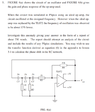
I have been given an assignment relating to RC phase shift oscillators. For me to confirm my findings I require a bode plot read out. However, after many attempts, countless videos and reading material I am still unable to achieve anything. Can some kind person point me in the right direction?.
Relevant Equations
Drawings attached.
Circuit schematic of an op-amp oscillator: a TL072 op-amp with a 33k feedback resistor R4, a 1k resistor R3 at the inverting input, three RC branches of C3, C2, C1 with 1k resistors R1 and R2 forming a feedback network, supplies of -5V and +5V, and output labelled Vout.

Bode plot, labelled Fig. 4(b): large-signal differential voltage amplification (log scale, 1 to 10^6) and phase shift (0 to 180 degrees) against frequency in Hz from 1 to 10M. Amplification falls from about 10^5 and phase shift runs from 0 to 180 degrees.

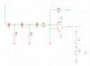
Circuit schematic of a third-order RC high-pass filter with a TL072 op-amp: three 1n capacitors C3, C1 and C2 in series, shunt resistors R1 and R2 at 1K to ground, R4 1K into the non-inverting input, and a 33k feedback resistor R3 with split supplies +v and -v, both 5 V.
 
Attachments
  • Simulator schematic of a TL072 op-amp circuit with a three-stage RC network: C3, C1 and C2 at 1n in series, R1 and R2 at 1K to ground, R4 at 1K, and feedback resistor R3 at 33k. Supply sources V1 and V2 at 5 are shown separately.
    1642530649865.png
    13.8 KB · Views: 224
  • Log-log Bode plot, FIG. 4(b): large-signal differential voltage amplification (1 to 10^6) and phase shift (0 to 180 degrees) against frequency in Hz from 1 to 10M. Amplification curve falls from about 10^5 near 10 Hz to 1 near 5 MHz; phase curve drops from 0 to 180 degrees.
    1642530667852.png
    12.1 KB · Views: 185
  • Circuit schematic of an op-amp oscillator: a TL072 op-amp with a 33k feedback resistor R4, a 1k resistor R3 at the inverting input, a three-stage RC ladder of C3, C2, C1 with 1k resistors R1 and R2, and supplies of -5V and +5V, output labelled Vout.
    1642530683268.png
    30.5 KB · Views: 249
I would start by simulating the circuit without closing the loop directly from the output to the input. Get the Bode Plot of the transfer function with a signal source driving the input first, then you can close the loop and run a transient plot to see if it starts up and oscillates. What are you looking for on the initial Bode plot to predict where the oscillation frequency should be? :smile:
 
  • Like
Likes   Reactions: Callum Plunkett
BTW, the Bode plot that is included in the problem appears to be the open-loop gain of a unity-gain stable opamp by itself. It's definitely not the Body plot they are asking you to find...
 
  • Like
Likes   Reactions: Callum Plunkett
berkeman said:
I would start by simulating the circuit without closing the loop directly from the output to the input. Get the Bode Plot of the transfer function with a signal source driving the input first, then you can close the loop and run a transient plot to see if it starts up and oscillates. What are you looking for on the initial Bode plot to predict where the oscillation frequency should be? :smile:
Thanks for the reply! I’ve calculated the frequency of oscillation of about 65kHz. I was hoping to graph both an ideal op-amp and a TH072 op-amp and compare them. Another issue I’m having is with the unwanted capacitances within the TL072 and how to determine the value of them. Unfortunately, op-amps are not something I deal with day to day so I am struggling a lot with this particular subject.
 
* At first, you should verify if the oscillation condition (Barkhausen) is fulfilled: Loop gain (somewhat larger than) unity with zero phase shift at the desired frequency fo.
* For this purpose, the loop gain (gain of the complete open loop) has to be analyzed (ac analysis, magnitude and phase) . You should open the loop at the node left to C3 for injecting an ac test signal.
* This analysis should be made for the ideal as well as real opamp model. You will notice a remarkable difference - caused by the unwanted (but unavoidable) reduced open-loop gain Aol as well as phase shift introduced by the real opamp model (if it is a good and realistic model).
* For this purpose, you should not use the graph as contained in the data sheet (and reproduced in your contribution). The graph shows a parasitic phase shift (at 65kHz) of zero deg which is not correct (too rough). To verify the real contribution of the opamp model you should perform a separate ac anylysis of the opamps open-loop gain Aol and phase response .
 
Last edited:
  • Informative
  • Like
Likes   Reactions: Callum Plunkett and berkeman
LvW said:
* At first, you should verify if the oscillation condition (Barkhausen) is fulfilled: Loop gain (somewhat larger than) unity with zero phase shift at the desired frequency fo.
* For this purpose, the loop gain (gain of the complete open loop) has to be analyzed (ac analysis, magnitude and phase) . You should open the loop at the node left to C3 for injecting an ac test signal.
* This analysis should be made for the ideal as well as real opamp model. You will notice a remarkable difference - caused by the unwanted (but unavoidable) reduced open-loop gain Aol as well as phase shift introduced by the real opamp model (if it is a good and realistic model).
* For this purpose, you should not use the graph as contained in the data sheet (and reproduced in your contribution). The graph shows a parasitic phase shift (at 65kHz) of zero deg which is not correct (too rough). To verify the real contribution of the opamp model you should perform a separate ac anylysis of the opamps open-loop gain Aol and phase response .
Yeah I thought that 65kHz was abit off as I calculated the single stage phase angle as 68 degrees each for the RC ladder network, when I was hoping for something along the lines of 60 degrees. Thanks for the pointers, I am going to make an attempt tomorrow.
 
LvW said:
* For this purpose, you should not use the graph as contained in the data sheet (and reproduced in your contribution). The graph shows a parasitic phase shift (at 65kHz) of zero deg which is not correct (too rough).
That plot is on the manufacturer data sheet for the TL072 Op-Amp. It shows the phase shift as 90° at 65kHz.

Cheers,
Tom
 
Tom.G said:
That plot is on the manufacturer data sheet for the TL072 Op-Amp. It shows the phase shift as 90° at 65kHz.

Cheers,
Tom
Yes - I know.
However, as I have mentioned (and as you can see), this diagramm is not exact enough for calculating the real phase shift within the loop. The simulation model is much more exact.
 
Callum Plunkett said:
Yeah I thought that 65kHz was abit off as I calculated the single stage phase angle as 68 degrees each for the RC ladder network, when I was hoping for something along the lines of 60 degrees. Thanks for the pointers, I am going to make an attempt tomorrow.
It’s been a while (sick family member and so on..) but I’ve finally found some time to give this another go. I recreated both circuits and inserted a bode plot, to the left of C3 to gain the following graphs. I’m not 100% certain that I have all the settings for the simulation set correctly or in a manner that would make the results clearer or even correct. Hopefully I’m somewhere near.
Screenshot of SIMetrix SIMPLIS schematic with an op-amp active filter circuit beside a Bode plot showing gain in dB and phase in degrees against frequency from 1 Hz to 10 MHz.


Screenshot of a SIMetrix simulation: a multi-stage RC op-amp circuit with AC source V3 and an ideal op-amp X1, beside a Bode plot of gain in dB and phase in degrees versus frequency from 1 Hz to 1 GHz.
 
..."both circuits..." What is the difference?
Circuit diagrams and both graphs are hard to read.
Which variables are shown in the diagrams?
Loop gain?
What is your outcome?