Discussion Overview
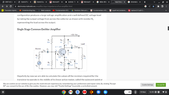
The discussion revolves around the calculation of input and output impedance in circuits involving parallel resistors, specifically in the context of a common emitter configuration. Participants explore the relationships between resistors R1, R2, RC, and RE, and how they affect impedance calculations.
Discussion Character
- Conceptual clarification
- Debate/contested
Main Points Raised
- Some participants question how resistors R1 and RC can be considered in parallel for impedance calculations, suggesting that examples typically show straightforward instances of parallel resistances.
- One participant asserts that R1 is in parallel with R2 and RC is in parallel with RE, while previously they were in series.
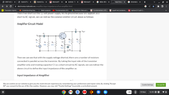
- Another participant challenges the assertion that R1 and RC are in parallel, asking for an equivalent circuit to clarify the impedance calculations.
- It is noted that the power supply can be treated as having zero impedance and constant voltage, which influences the impedance calculations.
- One participant emphasizes that the input and output impedances are defined by the change in voltage and current, referencing the formula for input impedance.
- Another participant argues that components cannot be considered in series if there is any alternative path for current, referencing the presence of a transistor with three terminals.
- A participant discusses the principle of superposition in calculating AC current, suggesting that R1 and R2 should be connected in parallel for AC impedance calculations.
- There is a remark that the conceptual understanding of these relationships may not be obvious to those learning the material.
Areas of Agreement / Disagreement
Participants express differing views on the configuration of resistors R1, R2, RC, and RE in terms of parallel and series connections, indicating that the discussion remains unresolved with multiple competing interpretations.
Contextual Notes
Participants reference the need for equivalent circuits and simulations to clarify their points, indicating potential limitations in their current understanding and the complexity of the circuit analysis involved.