DC blocking the photodiode signal

AI Thread Summary
The discussion revolves around issues with detecting a small optical signal using a Newport 818-bb-21 photodiode and a Thorlabs DC blocker, EF500. The user is experiencing a loss of both DC and AC signals after using the DC blocker, despite it functioning correctly with other signals. Participants suggest that the DC blocker may not be suitable for low-frequency signals and emphasize the importance of impedance matching, particularly a 50Ω load for proper operation. The user is advised to consider using the oscilloscope's AC coupling instead of the DC blocker and to clarify the circuit setup for better troubleshooting. The main goal is to amplify the signal while effectively removing the DC background noise.
kplee
Messages
22
Reaction score
0
Hi all,

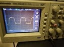
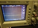
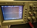
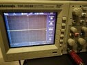
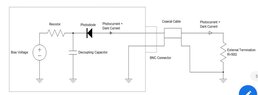
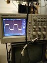
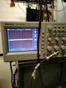
I was trying to detect small optical signal through amplification process and realized that there is a huge DC background behind the AC signal. So I decided to remove the background using a Thorlabs DC blocker (EF500). The photodiode I used was Newport 818-bb-21, and the signal before the blocker was ~5 mV heighted retangular waveform with 250 Hz frequency. However, it turned out that the signal gets messed with no DC and no AC after passing through the DC blocker. The attacheds are before/after signal from oscilloscope with DC/AC coupling. Could you help me out why it happened?
 

Attachments

  • PD signal_before_AC coupling.jpg
    PD signal_before_AC coupling.jpg
    70.6 KB · Views: 112
  • PD signal_before_DC coupling.jpg
    PD signal_before_DC coupling.jpg
    68.5 KB · Views: 89
  • PD signal_after_DC coupling.jpg
    PD signal_after_DC coupling.jpg
    69.8 KB · Views: 122
  • PD signal_after_AC coupling.jpg
    PD signal_after_AC coupling.jpg
    70.2 KB · Views: 109
Engineering news on Phys.org
Welcome to PF.

Can you upload a diagram of your circuit? Use the "Attach files" link below the Edit window to upload a PDF or JPEG version of it. Thanks.
 
berkeman said:
Welcome to PF.

Can you upload a diagram of your circuit? Use the "Attach files" link below the Edit window to upload a PDF or JPEG version of it. Thanks.
Hi berkeman,

I am not sure what you mean circuit. I don't know much about the circuit structure of the photodiode and DC blocker since they are all commercial one and I am not a electronic engineering major.
 
Oh, I thought you built up the photodiode circuit yourself. Can you link to the respective datasheets then? Thanks.
 
Maybe your HPF filter (DC block) thinks your signal is too slow to let pass. Looks like about 100usec rise time, so maybe 3-4KHz. Most all DC blocks are intended for RF applications (>10MHz at least). Do you know the impedances involved (source, load, filter, etc?).

You could make your own with a big capacitor. In a 50Ω system you would use about 10uF in series with your cable. This would give you a 159Hz HPF with about 1.5dB attenuation at 250Hz; i.e you would lose about 15% of your AC amplitude.

In my lab we would use a simple op-amp HPF at these low frequencies so we wouldn't need such a big capacitor.
 
berkeman said:
Oh, I thought you built up the photodiode circuit yourself. Can you link to the respective datasheets then? Thanks.
Here is the datasheet for both.
 

Attachments

DaveE said:
Maybe your HPF filter (DC block) thinks your signal is too slow to let pass. Looks like about 100usec rise time, so maybe 3-4KHz. Most all DC blocks are intended for RF applications (>10MHz at least). Do you know the impedances involved (source, load, filter, etc?).

You could make your own with a big capacitor. In a 50Ω system you would use about 10uF in series with your cable. This would give you a 159Hz HPF with about 1.5dB attenuation at 250Hz; i.e you would lose about 15% of your AC amplitude.

In my lab we would use a simple op-amp HPF at these low frequencies so we wouldn't need such a big capacitor.
The user manual said it blocks < 1 Hz signal, and I actually tested it for several different signals from different waveform generators. It worked perfectly, blocking DC and leaving AC, except the one from photodiode, which makes me more confused.
 
OK, I'm still not sure what your setup is, since you don't want to show us a simple block diagram or schematic. We are not clairvoyant. But it looks to me like the detector should have a DC reverse bias with the 50Ω load impedance shown in their schematic pulling one side to ground. If you put a DC block after the PD then you may not have the reverse bias they want.

So, let's go back to the question that we have both asked you before; what are your impedances? Are you using the 50Ω termination that the PD data sheet says you should?
 
Last edited:
  • Like
Likes sophiecentaur
DaveE said:
OK, I'm still not sure what your setup is, since you don't want to show us a simple block diagram or schematic. We are not clairvoyant. But it looks to me like the detector should have a DC reverse bias with the 50Ω load impedance shown in their schematic pulling one side to ground. If you put a DC block after the PD then you may not have the reverse bias they want.

So, let's go back to the question that we have both asked you before; what are your impedances? Are you using the 50Ω termination that the PD data sheet says you should?

Sorry for the inconvenience. The scheme is simple as follows:

Without DC blocker: PD - BNC cable - Oscilloscope
With DC blocker: PD - BNC cable - DC blocker - Oscilloscope

So you said I need a 50 Ohm load impedance after the PD to have the reverse bias. Since everything is connected with BNC cable and I am not familiar with this kind of electronics, which component should I use as a 50 Ohm impedance and how should I connect them with the current setup?
 
  • #10
kplee said:
Sorry for the inconvenience. The scheme is simple as follows:

Without DC blocker: PD - BNC cable - Oscilloscope
With DC blocker: PD - BNC cable - DC blocker - Oscilloscope

So you said I need a 50 Ohm load impedance after the PD to have the reverse bias. Since everything is connected with BNC cable and I am not familiar with this kind of electronics, which component should I use as a 50 Ohm impedance and how should I connect them with the current setup?
Instead of using a separate DC blocker, have you tried just setting your oscilloscope coupling on AC, 50 Ohms? Or is the knee frequency of the AC coupling for your 'scope not what you need?
 
  • #11
kplee said:
which component should I use as a 50 Ohm impedance and how should I connect them with the current setup?
If you need to introduce a 50Ω load across the line from one box to the other then use a BNC T Piece and connect a 50Ω load to the third port of the T (they are available with all types of connector). That will provide a 50Ω path to ground.

It would help a lot, for you and us, if you could commit yourself to an actual diagram. It's no surprise that Electrical Engineers use diagrams in pretty well all circumstances. Block diagrams are often the best way.

Do you have a data sheet on the 'DC blocker'? Most filters need specific source and load impedances.
 
  • #12
berkeman said:
Instead of using a separate DC blocker, have you tried just setting your oscilloscope coupling on AC, 50 Ohms? Or is the knee frequency of the AC coupling for your 'scope not what you need?
That part is okay, since I could see the signal from the AC coupling, show in the picture. What I need is the removal of DC noise.
 
  • #13
sophiecentaur said:
If you need to introduce a 50Ω load across the line from one box to the other then use a BNC T Piece and connect a 50Ω load to the third port of the T (they are available with all types of connector). That will provide a 50Ω path to ground.

It would help a lot, for you and us, if you could commit yourself to an actual diagram. It's no surprise that Electrical Engineers use diagrams in pretty well all circumstances. Block diagrams are often the best way.

Do you have a data sheet on the 'DC blocker'? Most filters need specific source and load impedances.
I think it doesn't work for my case. I tried to couple it as PD-BNC-T with 50 Ohm termination - oscilloscope. It seems the termination load eats all the signal and the oscilloscope shows nothing even without the DC blocker.

For the block diagram, the one for PD is all I have in the attached.

For the datasheet, I attached it as well. It says "use the source impedance of 50 Ohm and the load impedance of < 100 kOhm".
 

Attachments

  • Screenshot_20231109_111221_Acrobat for Samsung.jpg
    Screenshot_20231109_111221_Acrobat for Samsung.jpg
    13.1 KB · Views: 115
  • EF500-SpecSheet.pdf
    EF500-SpecSheet.pdf
    619.8 KB · Views: 97
  • #14
So basically this is how I ended up with the 50 Ohm termination, and no signal was shown. I wonder what I have missed or mixed up in this setup.
 

Attachments

  • 20231109_112114.jpg
    20231109_112114.jpg
    44 KB · Views: 115
  • 20231109_112125.jpg
    20231109_112125.jpg
    42.8 KB · Views: 85
  • #15
kplee said:
What I need is the removal of DC noise.
What is "DC noise"? You mean a DC offset? That is what the AC coupling on your 'scope does.

And what is your goal in using this circuit? Are you trying to just measure the power of the laser in your fiber, or are you working on a communication system of some sort? If you tell us what you are trying to accomplish, we can probably be of more help.

Also, do you have access to a spectrum analyzer that can work in your passband frequency range (lower frequency)? If you are just trying to measure the amplitude of that square wave receive signal, a spectrum analyzer is probably a good alternative...
 
  • Like
Likes dlgoff and sophiecentaur
  • #16
berkeman said:
What is "DC noise"? You mean a DC offset? That is what the AC coupling on your 'scope does.

And what is your goal in using this circuit? Are you trying to just measure the power of the laser in your fiber, or are you working on a communication system of some sort? If you tell us what you are trying to accomplish, we can probably be of more help.

Also, do you have access to a spectrum analyzer that can work in your passband frequency range (lower frequency)? If you are just trying to measure the amplitude of that square wave receive signal, a spectrum analyzer is probably a good alternative...
The main purpose of this is to amplify the signal with the preamplifier, and I thought DC background would ruin the amplification process if it dominates the real signal. As you might see the first pictures I uploaded, there is a huge DC background of ~ 5 V coming from photodiode (I actually checked it with multimeter as well) and the signal is only the order of 10 mV. So I decided to remove the DC offset by blocking it.

We don't have spectrum analyzer, but I can try to borrow it from somewhere if you insist to use it.
 
  • #17
What are the values of the Bias Voltage and the Resistor for this circuit? I'm having trouble finding them in the datasheet.
 
  • #18
kplee said:
For the datasheet, I attached it as well. It says "use the source impedance of 50 Ohm and the load impedance of < 100 kOhm".
the data sheet appears to specify ">100k" and not less than. That suits an ordinary scope input (1M or more). 50Ω would be cutting your levels down a lot!
 
  • #19
kplee said:
For the block diagram, the one for PD is all I have in the attached.

For the datasheet, I attached it as well. It says "use the source impedance of 50 Ohm and the load impedance of < 100 kOhm".
Sorry, where does it say that? And which model PD are you using out of the ones that are listed in the datasheet?
 
  • #20
berkeman said:
Sorry, where does it say that? And which model PD are you using out of the ones that are listed in the datasheet?
It's about the datasheet for DC blocker. The one I am using is 818-bb-21, and I think there is no information about the resistor. It says the VDC is 9 V, so i guess that is the bias voltage.
 
  • #21
Are you putting in that 9V bias voltage, or is it from an internal battery or something?
 
  • Like
Likes sophiecentaur
  • #22
berkeman said:
Sorry, where does it say that? And which model PD are you using out of the ones that are listed in the datasheet?
The >100k figure is on the picture of the DC blocker (output )
 
  • #23
Hmm, I don't get the need for a DC blocker if the 'scope AC input can be used instead. And I still don't understand the "DC noise" thing, since the dark current spec is <1nA, and the max signal allowed for this PD is 3mA peak into 50 Ohms...
 
  • #24
sophiecentaur said:
the data sheet appears to specify ">100k" and not less than. That suits an ordinary scope input (1M or more). 50Ω would be cutting your levels down a lot!
I thought that applies for the scope, not for the termination load in the middle. Also, the datasheet is for the DC blocker, and in the picture I didn't even use the DC blocker. As I said, I tried to measure the signal with 50 Ohm termination and without DC blocker, which didn't work.

Here is the scheme, and you can check it.

Scheme.jpg
 
  • #25
berkeman said:
Hmm, I don't get the need for a DC blocker if the 'scope AC input can be used instead. And I still don't understand the "DC noise" thing, since the dark current spec is <1nA, and the max signal allowed for this PD is 3mA peak into 50 Ohms...
As I said, I want extract the AC signal out of DC background and amplify it using the preamplifier. What I am measuring now is a test signal, not a real signal which is way smaller than this.
 
  • #26
berkeman said:
Are you putting in that 9V bias voltage, or is it from an internal battery or something?
It's the internal baatery
 
  • #27
So I'd get rid of the DC blocker and external 50 Ohm termination, and just use the AC coupling and 50 Ohm input setting on the 'scope.

Are you saying that with the 'scope set on 1M Ohm input, you get the 10mVpeak signal, and with it set on 50 Ohm input you don't see any signal? What is your optical power? Are you sure your fiber is aligned well where you are inserting the signal and at the PD? How long is the fiber? What optical wavelength are you using?

EDIT -- I missed your reply while I was typing...
kplee said:
As I said, I want extract the AC signal out of DC background and amplify it using the preamplifier. What I am measuring now is a test signal, not a real signal which is way smaller than this.
 
  • #28
kplee said:
What I am measuring now is a test signal, not a real signal which is way smaller than this.
What test signal? From where?
 
  • #29
berkeman said:
What test signal? From where?
I mean, the test signal from photodiode made by test optical input.
 
  • #30
Why did you choose that amplifier? Are you using it in powered or unpowered mode? It does not seem to be a good match for this application, unless you are planning on using the lock-in feature at some point.
 
  • #31
berkeman said:
Why did you choose that amplifier? Are you using it in powered or unpowered mode? It does not seem to be a good match for this application, unless you are planning on using the lock-in feature at some point.
I will use the lock-in at the end, actually. The thing is, If I use only lock-in without preamp I would not see the signal.

+ I have no choice but to use it because this is what our lab has. haha
 
  • #32
So presumably if you only use the 'scope, you see this?
  • Input Coupling = DC, 1M Ohm, get 9Vdc offset and AC signal too small to see
  • Input Coupling = AC, 1M Ohm, get 10mVpp square wave signal
  • Input Coupling = AC, 50 Ohm, the square wave signal is too small to see
Is that right?
 
  • #33
berkeman said:
So presumably if you only use the 'scope, you see this?
  • Input Coupling = DC, 1M Ohm, get 9Vdc offset and AC signal too small to see
  • Input Coupling = AC, 1M Ohm, get 10mVpp square wave signal
  • Input Coupling = AC, 50 Ohm, the square wave signal is too small to see
Is that right?
I am not sure whether I understand the coupling concept, but let me rephrase what you said in my version.

1. I coupled the PD signal directly to scope with BNC cable. I set the scope as DC coupling and saw ~ 3 Vdc offset (not 9, idk why)

2. I coupled the PD signal the same way as I did in 1). I set the scope as AC coupling and saw ~ 10 Vpp square waveform.

3. I coupled the PD signal to the scope through the T connection with the 50 Ohm termination at the third end. I set the scope as AC coupling and saw nothing.

Are we on the same page now?
 
  • #34
kplee said:
saw ~ 3 Vdc offset (not 9, idk why)
Does the PD battery need charging?

kplee said:
2. I coupled the PD signal the same way as I did in 1). I set the scope as AC coupling and saw ~ 10 Vpp square waveform.
10Vpp or 10mVpp?
 
  • #35
berkeman said:
Does the PD battery need charging?10Vpp or 10mVpp?
1) I am not sure but I think it is working at least.

2) Sorry, 10mVpp
 
  • #36
kplee said:
I mean, the test signal from photodiode made by test optical input.
Does that test signal come with any sort of data? What is the expected output from the PD when you use this test signal? The PD datasheet says 470mA/W of optical input power, and your 10mVpp into 1M Ohm implies 10nA...
 
  • #37
berkeman said:
Does that test signal come with any sort of data? What is the expected output from the PD when you use this test signal? The PD datasheet says 470mA/W of optical input power, and your 10mVpp into 1M Ohm implies 10nA...
How does that calculation happen? I thought it can be directly converted from the PD datasheet, which implies the PD current of ~ 4.7 uA ideally.
 
  • #38
kplee said:
How does that calculation happen? I thought it can be directly converted from the PD datasheet, which implies the PD current of ~ 4.7 uA ideally.
Sorry, where are you seeing that in the PD datasheet? I see this for the maximum linear photocurrent (your -21 model is the right-most column):
1699556130692.png
 
  • #39
kplee said:
How does that calculation happen?
##\frac{10mVpp}{1M \Omega} = 10nA##
 
  • #40
berkeman said:
##\frac{10mVpp}{1M \Omega} = 10nA##
Oh I see. I think I mixed up during the calculation. But somehow that doesn't make much sense since the optical input is around several uW, which corresponds to several uA. Anyway, I think that's not an important part for now. I can handle that later. The problem is how to match this signal with the DC blocker and the preamp.
 
Last edited by a moderator:
  • #41
kplee said:
optical input is around several uW, which corresponds to several uA.
So ##(10 \mu A) (50 \Omega) = 1mVpp##

You need to have a low resistance like ##50 \Omega## to ensure that the PD is reverse biased well. If you try to use a ##1M \Omega## measurement resistance, the PD will not be reverse biased and the frequency response will not be very good.

So if you use the DC blocking coax thing (which I think presents ##50 \Omega## on the input (female BNC side) and go into a good preamp, you should get a reasonable signal. You could also use a spectrum analyzer instead to take advantage of its better input sensitivity.
 
  • #42
BTW, I just checked my Tek 'scope which is a model similar to yours, and it does not seem to have the ability to switch the input coupling resistance from ##1M \Omega## to ##50 \Omega##. My LeCroy 'scopes do have that ability.
 
  • #43
berkeman said:
So ##(10 \mu A) (50 \Omega) = 1mVpp##

You need to have a low resistance like ##50 \Omega## to ensure that the PD is reverse biased well. If you try to use a ##1M \Omega## measurement resistance, the PD will not be reverse biased and the frequency response will not be very good.

So if you use the DC blocking coax thing (which I think presents ##50 \Omega## on the input (female BNC side) and go into a good preamp, you should get a reasonable signal. You could also use a spectrum analyzer instead to take advantage of its better input sensitivity.

Well, the thing is the signal already gets mixed up when passing through the DC blocker on the 50 Ohm side, as I showed you before (check the first pictures). I didn't even use the preamp yet.
 
  • #44
This is all really hard to follow, but it sounds to me like you don't have enough intensity on the detector in photoconductive mode to drive a 50Ω load, but you do have enough to see a signal into a high impedance (perhaps in photovoltaic mode).

As an aside, good communication skills about lab work is an important skill in EE world. The people you work for will need that, and it is likely to improve your own work. Slow down; document; ask good, complete questions.
 
  • #45
DaveE said:
This is all really hard to follow, but it sounds to me like you don't have enough intensity on the detector in photoconductive mode to drive a 50Ω load, but you do have enough to see a signal into a high impedance (perhaps in photovoltaic mode).

As an aside, good communication skills about lab work is an important skill in EE world. The people you work for will need that, and it is likely to improve your own work. Slow down; document; ask good, complete questions.

Okay. I was just not used to the language in this community since I am in physics and didn't have any chance to work on electronics before. I didn't mean to confuse you. I will keep it in mind.

About what you said, I am kind of confused because when we think about the Ohm's law the voltage at the high impedance like the one in the scope should not change no matter it is connected to the low load impedance like 50 Ohm. Based on that, I can assume that there should be no difference on the PD signal when I add the 50 Ohm termination on the third end of T connector, just like the last pictures I uploaded. Here are my questions:

1) What makes the difference on detecting the signal through the scope when the 50 Ohm termination is added?
2) If the signal is detected through the termination add-up, why does the signal only matter the 50 Ohm termination but not the high impedance in the scope?
 
  • #46
kplee said:
About what you said, I am kind of confused because when we think about the Ohm's law the voltage at the high impedance like the one in the scope should not change no matter it is connected to the low load impedance like 50 Ohm. Based on that, I can assume that there should be no difference on the PD signal when I add the 50 Ohm termination on the third end of T connector, just like the last pictures I uploaded. Here are my questions:

1) What makes the difference on detecting the signal through the scope when the 50 Ohm termination is added?
2) If the signal is detected through the termination add-up, why does the signal only matter the 50 Ohm termination but not the high impedance in the scope?
The PD is a high impedance current source, so the resistance you terminate it into determines the voltage level you will detect.

It might be possible to use a current mirror circuit to do a better job of detecting these small PD currents, but the best way is to use a good-quality preamp after the DC blocking circuit. The way that I usually implement photodiode detectors is with a negative voltage for the reverse bias...

1699573337402.png

https://www.electronics-tutorial.ne...current-to-voltage-converter/#google_vignette
 
  • #47
berkeman said:
The PD is a high impedance current source, so the resistance you terminate it into determines the voltage level you will detect.

It might be possible to use a current mirror circuit to do a better job of detecting these small PD currents, but the best way is to use a good-quality preamp after the DC blocking circuit. The way that I usually implement photodiode detectors is with a negative voltage for the reverse bias...

View attachment 335095
https://www.electronics-tutorial.ne...current-to-voltage-converter/#google_vignette

1) What I understand is that there are two terminations: one at the scope with high impedance, and the other at the 50 Ohm termination with low impedance. If this is correct, why does the low impedance affect much even in the presence of the high impedance which is used for the detection?

2) If I need a reverse bias operation, should I build my own circuit? I think that's too much thing for me... I am not confident enough to make a precise measurement circuit that is required on my experiment.

As you said, I am trying to do the best way, making a working DC blocking circuit before the preamp, and that's why I want to figure out how to make it. I actually tried to amplify the PD signal with/without DC blocker, and it didn't work for both cases. They didn't show any signal just like what's shown in the current DC blocking setup. I just want to know why the signal disappears.
 
  • #48
Have you looked at other photodetector modules? Your required bandwidth looks pretty low, and your power requirement is also low. You should be able to find an inexpensive PD module that works much better than this one, and gives you a ##50 \Omega## source impedance voltage source to drive the coax to the 'scope.
 
  • #49
The SR554 preamplifier has a DC Input Impedance of 0.5 Ohm.
The AC Input Impedance is 0.5 Ohm and 0.5H (in series) in parallel with 1.6uF.

The bandwidth looks marginal for a 250Hz square wave, you will certainly lose the fast edges.

You did not say if you were supplying power to the preamplifier and using the builtin preamplifier for an overall gain of 500. If you are using the preamplifier, realize that the maximum input level 14mV RMS.

For your initial testing with the 'scope, instead of using the SR554 you can put a 0.001uF capacitor in series with the 'scope probe and the PhotoDiode circuit. This should greatly reduce any DC voltage drift you are seeing. However you can expect about a 50% slope on the flat parts of the nice squarewave. Using a larger capacitor value will flatten the squarewave tops but increase any interference fron DC voltage shift.

The SR554 User Manual is available at:
SR554m.pdf

Cheers,
Tom
 
Last edited:
  • Like
Likes Delta Prime
Back
Top