Derivation of single slit diffraction formula

9 replies · 3K views · last reply
songoku
Messages
2,522
Reaction score
395
Homework Statement
This is not homework

Please see below
Relevant Equations
None
Two diagrams of a single slit: (a) parallel Huygens wavelet rays leaving every point across the slit width a, angled at theta; (b) two rays from the slit top and midpoint, with path difference one half a sin theta.

Textbook page titled Finding the Minima explaining single-slit diffraction, with ray diagram reference Figure 25.32b and the equations 1/2 a sin θ = 1/2 λ, a sin θ = λ, and 1/(2m) a sin θ = 1/2 λ for m = ±1, ±2, ±3.


I want to ask several questions regarding to the text:
1) Why do we find the minima of the diffraction? Why not the maxima?2) "Figure 25.32b shows two rays that represent the propagation of two wavelets: one from the top edge of the slit and one from exactly halfway down"

Why do we take point exactly halfway down? Why not like a third or a fifth down?3) " The other minima are found in a similar way, by pairing off wavelets separated by a distance of 1/4 a, 1/6 a, 1/8 a, ..., 1/(2m) a"

Again, why don't we take other values like 1/3 a, 1/5 a, 2/3 a?Is the answer to my first and third questions is because that's what we get from doing the experiment? The pattern suits for minima but not for maxima?

Thanks
 
songoku said:
1) Why do we find the minima of the diffraction? Why not the maxima?
If you wish you can do it. The obvious maxima is ##\theta=0## , a straight ray, that is boring.
 
  • Like
Likes   Reactions: songoku
anuttarasammyak said:
If you wish you can do it. The obvious maxima is ##\theta=0## , a straight ray, that is boring.
Single-slit diffraction pattern in red light: a bright central maximum flanked by dimmer, narrower fringes on either side, separated by dark bands.


Why not other maxima besides the center one?

Thanks
 
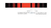
If you wish. I observe in your attached photo the width of the first minimum is narrower that that of maxima. It is convenient to observe. Thanks for the information.
 
  • Like
Likes   Reactions: songoku
songoku said:
Why do we take point exactly halfway down? Why not like a third or a fifth down?
In figure (b), the two rays cancel in a pair. Going down from them all the upper rays and downer rays make pairs for cancel so all the rays cancel. It does not work so for starting a third or fifth down.

songoku said:
Again, why don't we take other values like 1/3 a, 1/5 a, 2/3 a?

The chances for cancel follows as 1/4,1/6,1/8

For your favorite maxima why don't you investigate the case m is a half integer 3/2,5/2.7/2... ?
 
Last edited:
  • Like
Likes   Reactions: songoku
anuttarasammyak said:
I observe in your attached photo the width of the first minimum is narrower that that of maxima. It is convenient to observe. Thanks for the information.
Well, I don't understand why it is convenient to observe, I just post the picture from my book. But you are welcome

anuttarasammyak said:
In figure (b), the two rays cancel in a pair.
How can we know the two rays from the top edge of the slit and one from exactly halfway down will cancel? From the picture, the text just writes "finding minima". That's the reason I ask why not maxima.

I understand the path difference is ##\frac 1 2 a \sin \theta##, and then the text says: "if this extra distance is equal to ##\frac 1 2 \lambda##".
I don't understand this part. Why take the "if" as ##\frac 1 2 \lambda##, why not ##\frac 3 2 \lambda##? And also why we take the path difference to cause minima? Why not equate the path difference to ##\lambda## in the first place?

anuttarasammyak said:
For your favorite maxima why don't you investigate the case m is a half integer 3/2,5/2.7/2... ?
How to start doing the investigation?

Thanks
 
songoku said:
Well, I don't understand why it is convenient to observe, I just post the picture from my book. But you are welcome
Do not take it so seriously. I just thought as attached.
 
Attachments
  • Horizontal strip of single-slit diffraction intensity pattern in red and black, with a bright central band and dimmer fringes; annotations mark a narrow band labelled 'narrow' near the Total Cancellation position and a wider band labelled 'wide' near the Local Maximum position.
    211019.JPG
    13.3 KB · Views: 202
  • Like
Likes   Reactions: songoku
songoku said:
How can we know the two rays from the top edge of the slit and one from exactly halfway down will cancel?
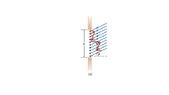
They cancel because they have wave length difference ##\lambda/2## in path length difference of an end and the middle of slit or phase difference of ##\pi##. As you say ##\lambda (n+1/2)## also works for n-th zero point. 
The above sketch is an illustrative explanation for n=1 [tex]\lambda=a \sin\theta[/tex]
Red line shows E strength, though perpendicular to plane actually, depending on the position. Sum of red vectors = 0. For n>1 there will be n wave trains between which results null in summation.
Diagram of single-slit diffraction: a slit of width a with evenly spaced point sources, plane waves arriving at angle theta, a red curve of phasors summing to zero, and a green line.
 
Attachments
  • Diagram of a single slit of width a with plane waves arriving at angle theta; red zigzag curves drawn at points across the slit show phasors cancelling, labelled (a).
    2110202.JPG
    8.3 KB · Views: 189
Last edited:
  • Like
Likes   Reactions: songoku
songoku said:
How to start doing the investigation?
You know minimum is simple to investigate, it is ZERO.
Maximum is, so to say, the Most Incomplete Cancellation Nearby.
Take "one - thirds case" you mentioned. The first two 1/3 cancel to zero. The remaining one 1/3 survive.
Changing 1/3 to 1/3+delta>0, The cancel portion increases so slit light becomes darker.
Changing 1/3 to 1/3- delta, The cancel portion decrease but new cancel portion appears so in total light becomes darker.
Thus you may know 1/3 case or more in general ##\lambda (n+ 1/2) ## in path length for full slit width provides a n-th local maximum. You see for larger n cancel portion increase more so the peak of brightness in maximum going downer.
Diagram of a single slit of width a with parallel rays of light hitting it at an angle, and a red zigzag path of phasor-like segments drawn across the slit, labeled (a).
 
Last edited:
  • Like
Likes   Reactions: songoku
I am really sorry for late reply

I need to re-read all you reply and try to understand it. Thank you very much for the help and explanation anuttarasammyak
 
  • Like
Likes   Reactions: Delta2