Determine pump spec necessary to overcome leak

In summary, the conversation discusses the sizing of a vacuum pump that is mounted on the ground and connected to a tree of overhead pipework at a height of 20ft. The pump must be able to provide sufficient vacuum to suck the 20ft head at any one line, even if all other lines are open to atmosphere. This involves calculating the flow rate of air in the plumbing and comparing it to the pump curve, as well as considering the specific gravity of the oil and potential pressure drops. The process also requires double checking calculations and taking into account altitude and flow restrictions.
  • #1
cameronrose97
3
2
TL;DR Summary
A vacuum pump is mounted on the ground, it is connected to 12 hose reels that extract oil from drain tanks, the pump must provide adequate suction at any one hose even if 11 are open to atmosphere.
A vacuum pump is mounted at ground level. The pump is connected to a tree of overhead pipework at a height of 20ft, connected to the pipework are 12 hose reels that can be attached to oil drain tanks. The client requests that the pump be sized so that sufficient vacuum can be achieved to suck the 20ft head at any one line even if all other lines are open to atmosphere. How does one go about determining pump size when accounting for a leak like this?

I suspect that what’s being requested wouldn’t be very efficient and might even be prohibitively expensive but I must do my due diligence and investigate.
 
Engineering news on Phys.org
  • #2
Although being oil it's not likely a problem, but first things first.

What is the density of the oil?
If it is greater than 2.17 pounds per in.3 there is not enough atmospheric pressure to push it up the needed 20ft.

What it comes down to is what is the flow rate of Air in the plumbing versus the pump curve. Which of course depends on the un-stated plumbing configuration.

Sounds like a problem for @jrmichler .
 
  • Like
Likes Lnewqban
  • #3
cameronrose97 said:
TL;DR Summary: A vacuum pump is mounted on the ground, it is connected to 12 hose reels that extract oil from drain tanks, the pump must provide adequate suction at any one hose even if 11 are open to atmosphere.

A vacuum pump is mounted at ground level. The pump is connected to a tree of overhead pipework at a height of 20ft, connected to the pipework are 12 hose reels that can be attached to oil drain tanks. The client requests that the pump be sized so that sufficient vacuum can be achieved to suck the 20ft head at any one line even if all other lines are open to atmosphere. How does one go about determining pump size when accounting for a leak like this?

I suspect that what’s being requested wouldn’t be very efficient and might even be prohibitively expensive but I must do my due diligence and investigate.
Draw the system, relative elevations of components, hose diameters, lengths, ect...
 
  • Like
Likes russ_watters
  • #4
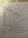
This is a straightforward fluid flow problem. It just needs to be solved in a series of steps. If, of course, I properly understand the OP. The sketch below shows what I think the OP is trying to do.
Vac System.jpg

Step 1: The OP needs to confirm that the above sketch is correct. If not, a correct sketch needs to be posted.

Step 2: The vacuum at P3 needs to be sufficient to lift the oil to that point, plus a little more to make the oil flow. It's a simple calculation involving the lift distance, the specific gravity of the oil, and the pressure drop of the oil at the desired flow rate. The air flow through the last hose is low enough that it can be considered to be zero.

Step 3: Given the vacuum in the header, and the length and diameter of the hoses, the air flow through the open hoses can be calculated. This will be a stepwise, iterative calculation because the pressure drop is more than 10% of the atmospheric pressure.

Step 4: Sum the airflow through the 11 open hoses. Size the header so that P2 is only slightly higher vacuum than P3.

Step 5: I'm assuming some sort of oil separator before the vacuum pump. That's the box between P1 and P2. Any oil separator will have a pressure drop. That pressure drop will further increase the vacuum at P1. Note that ACFM (Actual Cubic Feet per Minute) increases as the vacuum increases, so the ACFM at P1 will be greater than the ACFM at P2. Note that P1 should properly be shown at the pump inlet because you need the vacuum and ACFM at the pump inlet.

Step 6: Go back and double check your work. It is very easy to mess up calculations by not keeping proper track of vacuum vs absolute pressure. All flow calculations are done using absolute pressure, then converted to vacuum. You need to include your altitude above sea level because 1000 feet altitude is one inch mercury vacuum is about 0.5 PSI. That becomes significant at the vacuum in your system.

Step 7: You now have the atmospheric pressure, the vacuum at the inlet of the vacuum pump, and the flow rate in ACFM at the pump inlet. If there is a filter or silencer at the pump outlet, that flow restriction must be included in the system design. You now have the information to size a vacuum pump and oil separator.
 
  • Like
Likes russ_watters
  • #5
cameronrose97 said:
I suspect that what’s being requested wouldn’t be very efficient and might even be prohibitively expensive but I must do my due diligence and investigate.
Sorry, I'm not an ME or a pump guy, but why in the world would you not have some way to close off the lines that would be sucking air? There must be standard simple ways to do that, no?
 
  • Like
Likes russ_watters and erobz
  • #6
Thank you all for your responses, please allow me to elaborate and respond as follows:

- The oil density is relatively low at around 860kg/m3 (aprx .03lb/in3)
- I have attached a rough sketch of the plumbing configuration that my colleague intends to use for this system, by his own admission the plumbing is guesswork
- jrmichler, thank you, your response looks like something I can work through to come up with something quantifiable, I will see if I can work through it this evening
- Regarding closing off the open lines, this was my suggestion exactly, the response was that the system had to be automated and manual shut offs would be an issue (the pump will run intermittently on a timer). This is rubbish of course as there are practically an infinite number of ways that we could automate shut off valves either on a timed schedule or with an input from a float switch etc etc.

My feeling is that the brute force approach to this will lead to a large amount being spent on a pump that far exceeds our true needs. I shared this notion in our project meeting last week and now wish I'd kept my mouth shut. The problem has been itching away at me for a few days so it's really just a learning exercise now.
 

Attachments

  • 20221206_000002524_iOS.jpg
    20221206_000002524_iOS.jpg
    35.9 KB · Views: 56
  • Like
Likes berkeman
  • #7
cameronrose97 said:
- Regarding closing off the open lines, this was my suggestion exactly, the response was that the system had to be automated and manual shut offs would be an issue (the pump will run intermittently on a timer). This is rubbish of course as there are practically an infinite number of ways that we could automate shut off valves either on a timed schedule or with an input from a float switch etc etc.
No automation or manual shutoffs needed. I found lots of float-based shutoff valves for liquid-based piping with my Google Images search...
 
Last edited:
  • Like
Likes cameronrose97
  • #8
berkeman said:
No automation needed. I found lots of float-based shutoff valves for liquid-based piping with my Google Images search...
Yes Sir, you are correct, I misused the term, anything we don't have to touch is really what I meant!
 
  • Like
Likes berkeman
  • #9
Great! And part of your engineering analysis will include the added cost of the (inexpensive) float valves at each of the pump piping inlets versus the 50x (or more) increase in sizing the pump. You'll be the hero! :smile:
 
  • Like
Likes cameronrose97
  • #10
I have been in very similar situations. The realistic option for an engineer in that position is to do a complete concept design for two alternatives. Each concept design will include a properly sized pump and properly sized lines and hoses, with budget prices. The budget costs should be broken down to major components, not just one total summary cost for each system. Any motor more than about 5 hp should include the cost of the starter, necessary wiring, disconnect, and circuit breaker. Larger motors can have significant costs for necessary electrical changes, and those changes can go all the way to the main plant entrance panel. The engineer needs to check this. Ask me how I know this.

And never underestimate the bullheadedness of an authoritarian manager who demands that it be done his way. Again, ask me how I know this.

cameronrose97 said:
I suspect that what’s being requested wouldn’t be very efficient and might even be prohibitively expensive but I must do my due diligence and investigate.
This is absolutely correct. And expect it to take more than just this evening. BTDT.
 
  • Like
Likes Lnewqban, cameronrose97 and berkeman
  • #11
1) Why the vacuum pump?
2) How would the oil not reach that vacuum pump?
3) Do you need to extract gases while you are not evacuating oil?
4) Could individual small oil pumps (in pure pushing configuration) be located at each drain point instead?
 

1. What factors determine the necessary pump specifications to overcome a leak?

The necessary pump specifications to overcome a leak depend on the type and size of the leak, the fluid being pumped, the distance the fluid needs to be pumped, and the desired flow rate.

2. How do I calculate the required pump flow rate to overcome a leak?

To calculate the required pump flow rate, you will need to know the volume of fluid that needs to be pumped, the time frame in which it needs to be pumped, and the pressure required to overcome the leak. You can use the formula Q = V/t, where Q is the flow rate, V is the volume, and t is the time.

3. Can I use any type of pump to overcome a leak?

The type of pump needed to overcome a leak will depend on the type of fluid being pumped and the pressure required. For example, a centrifugal pump may be suitable for pumping water, but a positive displacement pump may be needed for thicker fluids like oil.

4. How do I determine the pressure required to overcome a leak?

The pressure required to overcome a leak can be determined by calculating the head loss in the system. This can be done using the Darcy-Weisbach equation or other head loss formulas. You will also need to consider the elevation difference between the pump and the leak and any additional friction losses in the system.

5. Is it better to oversize or undersize the pump for overcoming a leak?

It is generally better to slightly oversize the pump to ensure it can handle the necessary flow rate and pressure to overcome the leak. However, oversizing too much can lead to inefficiency and increased energy costs. It is important to carefully consider all factors and consult with a pump specialist to determine the best pump size for your specific application.

Similar threads

  • Mechanical Engineering
Replies
5
Views
1K
Replies
10
Views
2K
Replies
3
Views
11K
Back
Top