Determining Force and Directions on Truss with Pulley

  • Context: Engineering 
  • Thread starter Thread starter trusshelp148
  • Start date Start date
  • Tags Tags
    Force Pulley Truss
Join the discussion
Ask a follow-up here, or get your own question answered by working scientists, mathematicians and engineers — people, not an autocomplete.
Real named experts · corrections over time · the nuance an AI answer skips
7 replies · 3K views
trusshelp148
Messages
4
Reaction score
1
Homework Statement
I am struggling to figure out if I did this problem correctly. I am supposed to determine the forces acting on all of the links, as well as whether they are in tension or compression. There is an image included below.
Relevant Equations
∑Fx=0
∑Fy=0
∑M=0
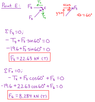
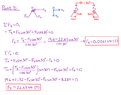
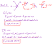
So far I have used methods of joints to determine the forces at point E, D, and C. However, there is also a pulley attached to point D and E which I included in the sum of forces, but I'm not sure if that's the correct way to apply them. Every force I've calculated so far has also been in tension, which does not seem right. I'm also unsure of how to calculate the reactions at A and B with the pulley involved. Any help would be much appreciated.
 

Attachments
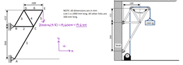
  • diagram.png
    diagram.png
    21.2 KB · Views: 285
  • Point E.png
    Point E.png
    13.1 KB · Views: 259
  • Point D.png
    Point D.png
    22.6 KB · Views: 226
  • Point C2.png
    Point C2.png
    17.9 KB · Views: 232
Physics news on Phys.org
Lnewqban said:
Welcome, @trusshelp148 !

My old eyes can barely distinguish anything in that image that you have included.
Could you improve it?
Thank you! And of course, sorry for the blurry view. I've attached some more photos that I hope are more viewable.
 
Thank you! :smile:
I would treat both pulleys as one.
The tension in the cable is the same everywhere.
Are those 2000 kg-mass or kg-force?
That weight is your tension, pushing D and E down and compressing link 6 from both ends.

Please, see:
https://www.ecourses.ou.edu/cgi-bin/ebook.cgi?topic=st&chap_sec=03.2&page=case_sol

Links 4 and 5 must be in compression, transferring that load down to node C, link 1 and pivot A.
Link 1 must be in compression, while ling 2 is pulling hard from pivot B.
Link 3 is not doing much, at least in theory.
 
Lnewqban said:
Thank you! :smile:
I would treat both pulleys as one.
The tension in the cable is the same everywhere.
Are those 2000 kg-mass or kg-force?
That weight is your tension, pushing D and E down and compressing link 6 from both ends.

Please, see:
https://www.ecourses.ou.edu/cgi-bin/ebook.cgi?topic=st&chap_sec=03.2&page=case_sol

Links 4 and 5 must be in compression, transferring that load down to node C, link 1 and pivot A.
Link 1 must be in compression, while ling 2 is pulling hard from pivot B.
Link 3 is not doing much, at least in theory.
It is 2000 kg-mass, yes. How would I go about treating the pulley as one? Since it's the same cable going through D and E, do I not need to apply it to the links multiple times?
 
trusshelp148 said:
It is 2000 kg-mass, yes. How would I go about treating the pulley as one? Since it's the same cable going through D and E, do I not need to apply it to the links multiple times?
Doing a FBD for each pulley, you will see that two compression forces go down the two links that meet at each.
Treat the cable as in equilibrium (Tin = Tout)
 
Lnewqban said:
Doing a FBD for each pulley, you will see that two compression forces go down the two links that meet at each.
Treat the cable as in equilibrium (Tin = Tout)
Thank you! I understand now.
 
Reply
  • Like
Likes   Reactions: Lnewqban
Triangle CDE is loading node C with (19.6 x 2) kN (straight down).
Calculating moments about pivots A, and then B, you can determine how much vertical and horizontal forces each is loaded with.
Only then, you will be able to visualize how each link is working.