Truss analysis problem

  • Thread starter jojosg
  • Start date
16 replies · 4K views · last reply
jojosg
Messages
47
Reaction score
5
Thread moved from the technical forums to the schoolwork forums.
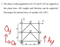
TL;DR: determine the internal force of member OA

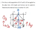
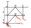
Hi I'm struggling with this problem. I have calculated the angle to be 45 degrees with tan(theta) = a/a. A is a roller which only has Ay and O has Ox & Oy as a fixed pin. (see fbd.png) is my FBD correct?
 
Attachments
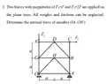
  • Plane truss diagram with joints E, D, C, G, H, B, O and A, labelled spans a, a and a, a. Force F2 = 2F points down at E and F1 = F points right at C. O is a pin support and A is a roller support. Handwritten red reactions Ox, Oy and Ay are added.
    fbd.webp
    32.5 KB · Views: 31
  • Plane truss diagram with joints O, G, E, H, D, C, B and A on a rectangular frame. Force F2 points down at E and F1 points right at C, with dimensions a marked on both height and width.
    truss.webp
    25.4 KB · Views: 42
jojosg said:
TL;DR: determine the internal force of member OA

Hi I'm struggling with this problem. I have calculated the angle to be 45 degrees with tan(theta) = a/a. A is a roller which only has Ay and O has Ox & Oy as a fixed pin. (see fbd.png) is my FBD correct?
In order not to have any movement or displacement in this system, the effects of both applied forces must be counteracted by those two supports, which are the only connection of that structure to the solid ground.

Therefore, your FBD should include all the ways in which those effects could reach those supports.

The directions of the forces potentially reaching each support coincide with the geometry of the connecting links, which are only able to transfer traction or compression forces.

Your FBD is missing the possible influence of links HO and HA.
 
Lnewqban said:
In order not to have any movement or displacement in this system, the effects of both applied forces must be counteracted by those two supports, which are the only connection of that structure to the solid ground.

Therefore, your FBD should include all the ways in which those effects could reach those supports.

The directions of the forces potentially reaching each support coincide with the geometry of the connecting links, which are only able to transfer traction or compression forces.

Your FBD is missing the possible influence of links HO and HA.
what if I take method of sections and use the left side?
 
Attachments
  • Plane truss diagram with joints labeled E, D, C, G, H, B, O and A, dimensions a, a, a, force F2 = 2F acting down at E and F1 = F acting right at C, supports at O and A, and a blue section line cutting through members.
    fbd.webp
    38.5 KB · Views: 38
A reaction in the hinge O has two components. A reaction in the hinge A has only a vertical component. We have three unknowns. Find them first by considering the equations of equilibrium for the whole construction as a rigid bod
 
Last edited:
wrobel said:
A reaction in the hinge O has two components. A reaction in the hinge A has only a vertical component. We have three unknowns. Find them first by considering the equations of equilibrium for the whole construction as a rigid bod
ok for Fy=0; Oy + Ay = 2F, Fx=0; Ox + F = 0, Ma=0; 2F(2a) - Oy(2a) - F(2a) = 0; which gives Oy = F & Ay = F & Ox = -F.
 
Attachments
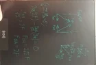
  • Handwritten truss analysis on a dark board in teal ink: load F_GH = 2F, moment sum about A equals zero giving F_OH/√2 = 2F, F_OH = 2√2 F, F_OA = 2F, with force triangle sketches of joint forces and a 45-degree right triangle with sides a, a, a√2.
    truss.webp
    16.9 KB · Views: 21
wrobel said:
I have got the same and my guess is that the internal force [in member OA] must be Ox
That would only be true if the tension in member OH were zero. But in the x-direction, the force-balance at point O is:
##-F~ +~ T_{OA}~ +~ T_{OH} \cos 45^ \circ = 0##
 
jojosg said:
what if I take method of sections and use the left side?
The way you've marked the 'cut' in your Post #3 diagram suggests that you may have misunderstood the method of sections.

A suitable cut is th red line:
Truss diagram with pins at O and A on a horizontal base, joints E, D, C on top, G, H, B in the middle, labelled a spacings; force F2 points down at E and F1 points right at C; a red diagonal cut line crosses members.


Consider the section above the red line as a single object. It has known external forces at O, E and C. There are 3 additional unknown external forces on the object: ##T_{AO}, T_{AB}## and ##T_{AH}## corresponding to the tensions in members AO. AB and AH;
Free-body diagram of a planar truss with labelled joints E, D, C, G, H, B and O, members drawn as lines, external forces F1, F2 and reactions Ox = F and Oy = F, and member tensions TAO, TAH and TAB shown as arrows.

[EDIT. Added ##O_x## and ##O_y## to image. ]

This new object is in equlibrium. By balancing its x-forces, y-forces and moments, you can find the 3 unkown forces (one of which is the required force).
 
Last edited:
Steve4Physics said:
That would only be true if the tension in member OH were zero. But in the x-direction, the force-balance at point O
yes I agree. Then the only possibility I see is to write equations of equilibrium for each rod.
 
wrobel said:
yes I agree. Then the only possibility I see is to write equations of equilibrium for each rod.
The 'Method of Sections' is a way around this. See Post #9 which is intended to start the OP solving the problem using this method.
 
Steve4Physics said:
The 'Method of Sections' is a way around this. See Post #9 which is intended to start the OP solving the problem using this method.
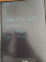
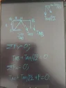
Like this?
 
Attachments
  • Handwritten equations in blue on an e-ink writing tablet: 2a(-T_AH/√2) - 2a[(-T_AH/√2)] + 2a[-T_A0 - T_AH/√2] = 0, then -T_A0 = T_AH/√2, then F = 0.
    3.webp
    11.8 KB · Views: 43
  • Handwritten moment equilibrium working on an LCD writing tablet: sum of M0 = 0, a counterclockwise positive sign, (-TAH/√2)(a)·2 - TAB(2a) + 2a(F) = 0, F = -TAO - TAH/√2, and TAB = -TAH/√2.
    2.webp
    12.4 KB · Views: 45
  • Handwritten truss joint analysis on a tablet: a small truss with joints G, H, B, O and members labelled a, with forces TAH, TAB and TAO; equations ΣFy = 0 with TAB + TAH/√2 = 0, and ΣFx = 0 with TAO + TAH/√2 + F = 0.
    1.webp
    15.5 KB · Views: 43
jojosg said:
Like this?
You are on the right track but it looks like you have ignored some forces when expressing ##\Sigma F_x=0, ~\Sigma F_y=0## and ##\Sigma M=0##. (But see EDIT at bottom).

You found that ##O_x=-F## (i.e. F acting to the left) and ##O_y = F##.

With the bottom-right section removed, the new object in equilibrium, with all of its external forces shown, is this:
Free-body diagram of a blue truss section with external forces: 2F pointing down at the top left, F pointing right at the top right, F pointing up and F pointing left at the bottom left corner labelled O, and forces labelled TAB, TAO and TAH at the lower right edges.

(Note that ##A_y## is not needed as it was an external force acting on the section that has been removed.)

Use of ##\Sigma F_x=0, ~\Sigma F_y=0## and ##\Sigma M=0## requires that all the forces shown on the above diagram are considered.
_________________
EDIT.
Your working may well be correct but unfortunately I can't follow it in your 3 diagrams. However, your final statement ("F=0") can't be correct as F is an arbitrary external force (not the force you are required to find).

For clarity/readability, equations here should be written using LaTeX. The link to the LateX Guide appears at the bottom-left of the edit-window. Or, for convenience, here it is: https://www.physicsforums.com/help/latexhelp/
 
Last edited:
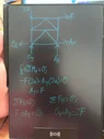
[tex]\sum M_0 = 0[/tex]
[tex]-F(2a) + A_y(2a) = 0[/tex]
[tex]A_y = F[/tex]

[tex]\sum F_x = 0[/tex]
[tex]F + A_x = O_x[/tex]

[tex]\sum F_y = 0[/tex]
[tex]O_y + A_y = 2F[/tex]

[tex]\sum M_A = 0[/tex]
[tex]-F(2a) + 2F(2a) - O_y(2a) = 0[/tex]
[tex]F = O_y[/tex]

[tex]F = O_x - A_x[/tex]

[tex]\sum F_y = 0[/tex]
[tex]-2F - \frac{F_{OH}}{\sqrt{2}} = 0[/tex]

[tex]O_x = 2F[/tex]
[tex]A_x = F[/tex]

Summary:
[tex]\boxed{A_y = F}[/tex]
[tex]\boxed{A_x = F}[/tex]
[tex]\boxed{O_x = 2F}[/tex]
[tex]\boxed{O_y = F}[/tex]
 
Attachments
  • Handwritten free-body diagram of a square truss with diagonals, loads 2F and F applied and reactions Ox, Oy, Ax, Ay labelled, with equilibrium equations written beneath.
    1.webp
    18.8 KB · Views: 32
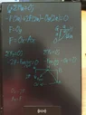
  • Handwritten truss analysis on a dark LCD writing tablet, with blue equations for moment and force balance, a triangle with sides labeled a, a and √2a, and a truss diagram with joints G, H, A, B and forces 2F, F_OH and O_x.
    2.webp
    19.2 KB · Views: 34
Last edited:
jojosg said:
[tex]\sum M_0 = 0[/tex]
[tex]-F(2a) + A_y(2a) = 0[/tex]
[tex]A_y = F[/tex]

[tex]\sum F_x = 0[/tex]
[tex]F + A_x = O_x[/tex]

[tex]\sum F_y = 0[/tex]
[tex]O_y + A_y = 2F[/tex]

[tex]\sum M_A = 0[/tex]
[tex]-F(2a) + 2F(2a) - O_y(2a) = 0[/tex]
[tex]F = O_y[/tex]

[tex]F = O_x - A_x[/tex]

[tex]\sum F_y = 0[/tex]
[tex]-2F - \frac{F_{OH}}{\sqrt{2}} = 0[/tex]

[tex]O_x = 2F[/tex]
[tex]A_x = F[/tex]

Summary:
[tex]\boxed{A_y = F}[/tex]
[tex]\boxed{A_x = F}[/tex]
[tex]\boxed{O_x = 2F}[/tex]
[tex]\boxed{O_y = F}[/tex]
I'm out for most of today but will take a look when I return.
 
@jojosg, there are a number of issues, so it's complicated to explain. But here is an attempt...

I've written some of your equations from Post 14, so that LaTeX renders them correctly (for me anyway). This required putting a pair of hash symbols (## \# \# ##) at the beginning and end of each equation.

So, the first part of your Post 14 working (with some comments aded) is this:
__________________________________

##\sum M_0 = 0##
##-F(2a) + A_y(2a) = 0##
##A_y = F##
That looks OK.
___________________________________

##\sum F_x = 0##
##F + A_x = O_x##
Not really. There is a roller at point A. There is no external horizontal reaction from a (perfect) horizontal roller. So you know in advance that ##A_x=0##..

If you don’t use this fact (that ##A_x=0##), then you have thrown away critical supplied information; this may prevent you from finding the correct answer.

The only 2 horizontal external forces are ##O_x## at point O and ##F_1## at point C.
___________________________________

##\sum F_y = 0##
##O_y + A_y = 2F##
That looks OK.

You already found that ##A_y = F##. So it follows that ##O_y=F##. You don't need your next step...
___________________________________

##\sum M_A = 0##
##-F(2a) + 2F(2a) - O_y(2a) = 0##
##F = O_y##

That's OK. but it is an unecessary step, as already noted.
___________________________________

##F = O_x - A_x##
But ##A_x## is known to be zero. See above.
___________________________________

##\sum F_y = 0##
##-2F - \frac{F_{OH}}{\sqrt{2}} = 0##
Not clear about this. It looks like you are referring to the system with a cut to remove the bottom-left section.

It appears you have assumed member GO has a tension of 2F and member AO has a tension equal to ##O_x##. That's wrong.

You need to redraw your diagram to show all external forces: carefully examine the Post #13 comments and diagram.
___________________________________

Additional note.

You have marked ##O_x## on a diagram as pointing left. By convention, an unknown x-component is assumed positive (pointing right, in the +x direction). With this corrected, ##O_x = -F##.

You can then (on a subsequent diagram) show this as a force F pointing left. Care is needed to avoid introducing sign-errors.

There may be other issues I've missed.

Minor edits (& again).
 
Last edited:
Been trying for a While. All I know after these is to take moment about O in the sectioned FBD but I keep getting redundant equation that do not let me find internal force Toa.
1. Global Equilibrium

Sum of moments about point B:

##\sum M_B = 0##

##-F(2a) + A_y(2a) = 0##

##A_y = F##

Sum of vertical forces:

##\sum F_y = 0##

##O_y + A_y = 2F##

##O_y + F = 2F##

##O_y = F##

Sum of horizontal forces:

##\sum F_x = 0##

##O_x + F = 0##

##O_x = -F##

3. Equilibrium Equations

Sum of moments about point H:

##\sum M_{H}=0##

##2F(a)-F(a)-F(a)+T_{OA}(a)-F(a)-T_{AB}(a)=0##

##T_{OA}-T_{AB}=F##

##T_{AB}=T_{OA}-F##

Sum of horizontal forces:

##\sum F_{x}=0##

##T_{OA}+\frac{T_{AH}}{\sqrt{2}}=0##
 
Attachments
  • Truss diagram with joints labeled E, D, C, G, H, B, O and A in a two-panel frame of width 2a and height 2a. Loads 2F downward at E and F rightward at C; reactions O_X, O_Y and A_Y shown.
    1.webp
    13.5 KB · Views: 39
  • Free-body diagram of a truss with labelled joints E, D, C, G, H, B and O, load 2F downward at E, F to the right at C, supports O_x and O_y, and member forces T_AH, T_AB and T_OA cut by a red section line, with dimension a on the left side.
    2.webp
    16.5 KB · Views: 39