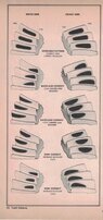
Difference between contact pattern and mounting distance for a pinion gear?

  • Thread starter Thread starter Ahmad anbar
  • Start date Start date
  • Tags Tags
    Contact
AI Thread Summary
The discussion clarifies the difference between contact pattern and mounting distance for a pinion gear in differential rebuilds. Contact pattern refers to the wear pattern on the gear face, which is assessed using machinist bluing to ensure proper teeth contact and avoid noise. Mounting distance is the ideal dimension for pinion and carrier placement, which often differs due to manufacturing imperfections. Adjustments are made using shims to achieve the correct contact depth and backlash for optimal gear performance. Properly aligning these factors is crucial for minimizing gear noise and ensuring efficient operation.
Ahmad anbar
Messages
1
Reaction score
0
TL;DR Summary
Hi
What is the difference between contact pattern and mounting distance pinion gear .
Is it possible for one to cancel the other?
Hi What is the difference between contact pattern and mounting distance pinion gear . Is it possible for one to cancel the other?
 
Engineering news on Phys.org
Welcome to Physics Forums.
A diagram or reference link would help us all understand what you're talking about.
 
  • Like
Likes Ahmad anbar
when doing a rebuild on the differential, correct wear pattern must be determined for best results. We do not want gear noise or rear end noise caused by improper teeth contact between the differential side gears and the pinion gear teeth. We paint the pinion with machinist bluing ( cheap blue dye) and rotate the assembly. we then check wear pattern on the gear face. If not correct we shim the pinion to achieve proper pattern.
We also have carrier shims that adjust backlash. Both the pinion and carrier have a Nominal Mounting distance or the ideal dimension but due to manufacturing imperfections in the gear making process the ideal and the real world dimensions will almost never be the same so we use the bluing method to check wear pattern. By adding or removing shims we adjust the contact depth ( pinion shim) and backlash ( carrier shim) to obtain optimum gear contact.
video below fast forward to 5 minutes 30 sec


Attachments

  • pinion spacer_000073.jpg
    pinion spacer_000073.jpg
    30.8 KB · Views: 66
Last edited:
  • Like
  • Informative
Likes Ahmad anbar, sophiecentaur and berkeman
Posted June 2024 - 15 years after starting this class. I have learned a whole lot. To get to the short course on making your stock car, late model, hobby stock E-mod handle, look at the index below. Read all posts on Roll Center, Jacking effect and Why does car drive straight to the wall when I gas it? Also read You really have two race cars. This will cover 90% of problems you have. Simply put, the car pushes going in and is loose coming out. You do not have enuff downforce on the right...
I'm trying to decide what size and type of galvanized steel I need for 2 cantilever extensions. The cantilever is 5 ft. The space between the two cantilever arms is a 17 ft Gap the center 7 ft of the 17 ft Gap we'll need to Bear approximately 17,000 lb spread evenly from the front of the cantilever to the back of the cantilever over 5 ft. I will put support beams across these cantilever arms to support the load evenly
Thread 'What's the most likely cause for this carbon seal crack?'
We have a molded carbon graphite seal that is used in an inline axial piston, variable displacement hydraulic pump. One of our customers reported that, when using the “A” parts in the past, they only needed to replace them due to normal wear. However, after switching to our parts, the replacement cycle seems to be much shorter due to “broken” or “cracked” failures. This issue was identified after hydraulic fluid leakage was observed. According to their records, the same problem has occurred...
Back
Top