Drawbridge falling before caught by rope/cable - Max force

Click For Summary

Discussion Overview

The discussion revolves around the forces exerted on a cable when a drawbridge, pivoted at a lower hinge, falls freely before being caught by the cable. Participants explore the dynamics involved in transitioning from slack to taut in the cable, considering aspects of rotational kinetic energy and the properties of the cable, including its behavior under tension.

Discussion Character

  • Exploratory
  • Technical explanation
  • Mathematical reasoning
  • Debate/contested

Main Points Raised

  • One participant proposes modeling the cable as a spring with a spring constant and suggests incorporating a dashpot to account for energy dissipation during the arrest of the falling bridge.
  • Another participant mentions that even a stiff steel cable will exhibit spring-like behavior when taut, up to its ultimate tensile strength.
  • There is a discussion about relating rotational kinetic energy to tension in the cable, with one participant questioning how to derive this relationship.
  • A participant suggests that the maximum extension of a steel wire rope before failure is 1%, and proposes calculating the energy stored based on the rope's dimensions and Young's Modulus.
  • One participant expresses concerns about the accuracy of their calculations, suggesting that cables may not obey Hooke's law, which could affect the results.
  • Another participant emphasizes the importance of treating the problem as an impact scenario rather than focusing solely on the rope's properties.
  • There is a technical discussion on converting linear spring constants to rotational spring constants, highlighting the complexities involved in combining linear and rotational motion.

Areas of Agreement / Disagreement

Participants express various viewpoints on how to model the system, with some advocating for a spring model while others suggest a focus on impact dynamics. There is no consensus on the best approach or the accuracy of the calculations presented.

Contextual Notes

Participants note limitations related to assumptions about the cable's behavior, the complexities of combining linear and rotational dynamics, and the potential inaccuracies in applying Hooke's law to cables under certain conditions.

Who May Find This Useful

This discussion may be of interest to engineers, physicists, and students exploring dynamics, material properties, and impact analysis in mechanical systems.

timotola
Messages
6
Reaction score
2
Hi,

I'm currently looking into the forces exerted on a cable if the cable was to go from slack to taut due to a falling object that is pivoted about a lower hinge - such as a drawbridge but instead of slowly lowering, there is slack in the cable causing the bridge to freely rotate about the lower hinge before arresting by the cable once the slack is taken up.

I'll attach a rough sketch to visualise what I'm thinking.

IMG_20210902_155414.jpg


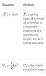
I'm assuming that the bridge starts at angular velocity = 0 in the upright position before finishing as drawn. I'm also understanding that the cable must undergo some extension to calculate the tension based on the rotational kinetic energy, hence, there should be a spring constant type property for the cable?

Any guidance on this one will be much appreciated, thanks.
 
Physics news on Phys.org
Welcome to PF.

timotola said:
hence, there should be a spring constant type property for the cable?

Yes, I would start modeling it as a spring with spring constant ##k## and add some lossy element like a dashpot. You can look up the ##k## and loss data for ropes like (dynamic) climbing ropes, where their behavior for the first few fall arrests is important. The spring and dashpot don't engage until the panel is at the angle where the rope would go taut.

https://en.wikipedia.org/wiki/Dashpot
 
Last edited:
berkeman said:
Thanks for the response, very interesting to use a dashpot type of element to reduce the force on the cable due to the momentum - would make a lot of sense in safety products.

Taking it back to its basic form however, without any kind of dampener and assuming a very stiff (steel type) cable, how would you recommend relating the rotational kinetic energy to the tension in the cable?

Thanks again.
 
Even with a very stiff steel cable, I believe it will act like a spring when pulled taut, at least up to the limit of its ultimate tensile strength:

https://en.wikipedia.org/wiki/Ultimate_tensile_strength

In the real world, dropping that platform and catching it only with a steel cable is going to put lots of stresses on the cable and attachments and the structures. What is the application?
 
berkeman said:
Even with a very stiff steel cable, I believe it will act like a spring when pulled taut, at least up to the limit of its ultimate tensile strength:

https://en.wikipedia.org/wiki/Ultimate_tensile_strength

In the real world, dropping that platform and catching it only with a steel cable is going to put lots of stresses on the cable and attachments and the structures. What is the application?
Yes I'm assuming the steel cable will still have some extension and act like a spring for a short while. I'm mainly wondering how to relate this to find the tension in the cable and hence the stress.

The application is similar to the drawbridge example but focused on if the main cable was to break, this secondary slack cable would take the load after a short fall.

Thanks again for the help, much appreciated.
 
Screenshot_20210902_173330.jpg

Would I be correct in setting the second equation equal to the rotational kinetic energy before rearranging for x. Then substituting this for x in the first equation where F would be the tension in the cable? Then find an appropriate stiffness value, k, to solve?
 

Attachments

  • Screenshot_20210902_173330.jpg
    Screenshot_20210902_173330.jpg
    16.5 KB · Views: 156
You have the right idea: Knowing the kinetic energy and the rope stiffness, solve for maximum deflection. Then substitute the maximum deflection into the force and spring constant equation.

That's easy for linear systems, it's more challenging for a linear spring on a rotational system. You need to convert the linear spring constant to a rotational (torsion) spring constant. A linear spring constant has units of lbs/inch (or N/m), while a torsion spring constant has units of inch-lbs/radian (or n-m/radian). You can calculate the torsional spring constant equivalent to the linear spring constant from the linear spring constant and the perpendicular distance from the cable to the center of rotation. The torsional spring constant depends on the distance from the cable to the center of rotation.

For general information on steel cables, search wire rope handbook. This is a good hit: https://www.unionrope.com/Portals/0/Documents/Technical/Wire-Rope-Basics/wire-rope-handbook.pdf.

Information on wire rope stiffness is a little harder to find. Search wire rope stiffness or wire rope axial stiffness to start. This is a good hit: https://core.ac.uk/download/pdf/288388769.pdf.
 
  • Informative
  • Like
Likes   Reactions: timotola and berkeman
Incredibly helpful information (I must admit I would've used the linear spring constant if you hadn't mentioned).

Thanks for the extra sources on cable related theory, again, very useful.

All the best and thanks again for the guidance.
 
  • Like
Likes   Reactions: jrmichler and berkeman
  • #10
As an engineering problem, I have found that the max extension for a steel wire rope before failure is 1%. We can then work out the energy stored from length, diameter and Young's Modulus.
Then we find the KE of the falling bridge and find an available rope with the required stored energy capacity.
In practice, of course, we would apply a large safety factor, maybe 12 for this sort of application.
 
  • #11
So, I've had a go at this with some example numbers and have come across some pretty poor results. I've either made a significant error that I can't spot or, the fact that cables don't obey Hooke's law has had a large effect on the final calculations.

I'll attach my working on this for now while I try and think of alternative routes to calculating the safety factor in this case.

Any help, recommendations or guidance will be hugely appreciated!

IMG_20210910_131142.jpg

IMG_20210910_131150.jpg
 
  • #12
This is just my roughly calculated suggestion:-
I presume the drawbridge falls down to horizontal. It has an initial GPE of 0.25 Lg m g.
GPE = 0.25x1x150x 10 = 375 J.
When it reaches horizontal, the GPE is converted to KE.
The KE is absorbed by the rope.
Let's assume the rope length is 1.4 m. It can stretch by 1% before failure = 0.014m.
Average Force in rope = 0.5 x Energy / Distance
= 0.5 x 375 / 0.014
= 13,392 N
So you need a rope with a breaking strength of 13,392 N (or in everyday language 1.3 tonnes).
 
  • Like
Likes   Reactions: timotola
  • #13
I rather suspect that the intention for this problem is not to model the rope at all, but to treat this as an impact problem. The rope is simply the means by which a force is suddenly applied to instantaneously stop the falling bridge.
 
  • #14
Problems combining linear and rotational motion can be challenging. In this case, the center of gravity (CG) of the drawbridge has an initial height, and a final height. The difference, ##\delta h##, is the vertical distance that the CG moves from the start of movement until stopped by the cable. That potential energy is equal to the kinetic energy at the instant that the cable stops the motion. The kinetic energy is rotational - ##0.5J\omega^2##, not linear - ##0.5mv^2##.

Drawbridge.jpg

In a rotational system with a linear spring, the linear spring constant needs to be converted to a rotational spring constant. The same spring connected to a point near the center of rotation will have a lower rotational spring constant than if connected to a point far from the center of rotation.

The rotational spring constant has units of ##Nm/radian##, and is calculated from the linear spring constant and the perpendicular distance from the spring centerline to the center of rotation. The perpendicular distance is shown as the dashed line in the sketch above. The rotational spring constant ##K_r = K_sD^2##, where:

##K_r## is the rotational spring constant, with units of ##Nm/radian##
##K_s## is the linear spring constant
##D## is the perpendicular distance from the spring centerline to the center of rotation

Rotational spring impact calculations are similar to linear spring impact calculations:

Linear: ##0.5mV^2 = 0.5K_sx^2##, where ##x## is the maximum spring deflection.
Rotational: ##0.5J\omega^2 = 0.5K_r\alpha^2##, where ##\alpha## is the maximum spring deflection.

In a linear system, the peak spring force is calculated directly from the peak spring deflection. In a rotational system, the peak spring deflection is calculated from the peak angular deflection, the distance from the center of rotation to the spring attach point, and the angle between the spring centerline and the drawbridge. A careful diagram and trigonometry is needed. The peak force is then calculated from the peak linear spring deflection and spring constant.
 
  • Like
  • Informative
Likes   Reactions: timotola, Lnewqban and berkeman

Similar threads

  • · Replies 5 ·
Replies
5
Views
3K
  • · Replies 3 ·
Replies
3
Views
2K
Replies
22
Views
3K
Replies
2
Views
2K
Replies
1
Views
7K