Drawing circuits with NAND gates

  • Context:
  • Thread starter Thread starter shamieh
  • Start date Start date
  • Tags Tags
    Circuits Drawing
Join the discussion
Registration is free. Ask a follow-up in this thread, or start your own.
4 replies · 3K views
shamieh
Messages
538
Reaction score
0
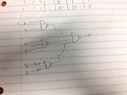
A cheap way to implement this circuit is to use only NAND gates. Draw the circuit diagram for the lowest cost implementation using these gates. (reminder: you can wire a NAND gate such that it acts like an inverter).

$f$(w,x,y,z) = $$x*y + w*x + \bar{y}*\bar{z}$$

My solution:
View attachment 1448 Will this work?
 

Attachments
  • photo(1).JPG
    photo(1).JPG
    22.4 KB · Views: 138
Physics news on Phys.org
shamieh said:
Will this work?
Close, but the problem statement says you can use only NAND gates, in particular, no NOT gates. However, NOT is easily expressible through NAND.

logic-gates1.png
 
Wow the fact that you got that your drew that diagram on here is awesome lol. But where is the y y and z z coming from? aren't those unnecesarry?
 
shamieh said:
But where is the y y and z z coming from? aren't those unnecesarry?
I don't understand the question, "Where are they coming from?". Do you know where x is coming from? What's the difference between x and y?
 
Nevermind, I see now.