Electronic Circuits - Calculate voltage

  • Thread starter Thread starter agatha
  • Start date Start date
  • Tags Tags
    Elecricity
Join the discussion
Registration is free. Ask a follow-up in this thread, or start your own.
4 replies · 2K views · last reply
agatha
Messages
2
Reaction score
0
Thread moved from the technical forums to the schoolwork forums
TL;DR Summary: Electronic Circuits

How do I calculate the voltage v1 using KCL?
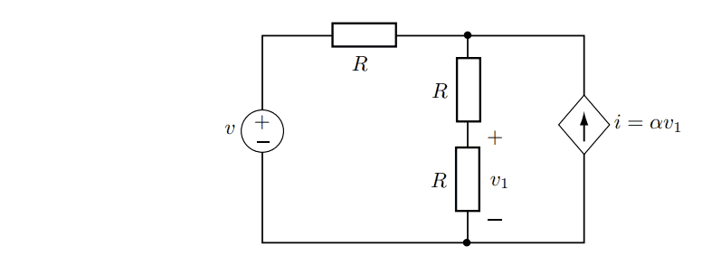
Circuit schematic with a voltage source v on the left in series with resistor R at top, a vertical branch of two resistors R with node voltage v1 across the lower one, and a dependent current source i = αv1 on the right.

I don't understand how I should express the current I3 to get the equation right.
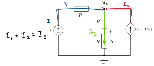
Circuit schematic with a voltage source v, series resistor R on top branch labelled v and Vx, two series resistors R in a vertical branch with voltage v1 across the lower one, and a dependent current source i = αv1 on the right; currents I1, I2, I3 are marked with the handwritten note I1 + I2 = I3, and the bottom wire is grounded.


I already watched this video but I don't know what to do when there are two resistors.
 
Physics news on Phys.org
This is the equation I should be getting but I don't know how to get there
Equation: v1/R + (2v1 - v)/R - αv1 = 0, written as typeset mathematics.
 
The answer they give has the form of, I3 + I1 - I2 = 0 ;
Your I1 has the opposite circulation to their assumption.
Vx = 2 * V1 ;
I1 = ( 2 * V1 - V) / R ;
I2 = α * V1 ;
I3 = V1 / R .
 
Normally for HW type problems, we don't like to just give answers without some teaching.
So now that we have @Baluncore's suggestions, I suggest you look at each of his steps and compare to the schematic to see why/how he concluded each item. For example, why does Vx = 2 * V1, etc? Then see how those combine to give the equation you were supposed to derive.

Let us know if you are still confused. Do you think you could solve a similar problem yourself now?
 
agatha said:
This is the equation I should be getting but I don't know how to get there
1711695014513.png
It is impossible to solve this problem using only two rules, the junction rule expressed by $$ I_1 + I_2 = I_3 $$ and the rule expressed by $$ v_1 = I_3 R $$ which is called Ohm’s law. Here must be applied one more rule, the loop rule (https://en.wikipedia.org/wiki/Kirchhoff's_circuit_laws). The equation $$ v - I_1 R - v_1 - v_1 = 0 $$ presents the loop rule for the left loop in the schematic diagram and after including it the final equation $$ \frac{v_1}{R} + \frac{2v_1-v}{R} - \alpha v_1 = 0 $$ will be got.