Gold Member
- 4,195
- 2,389
ArnoVonck said:Yes the impeller has been replaced with a completely new one. Both have been balanced, statically and dynamically.
.....
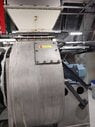
There is most certainly some deposits on the vanes. But the problem was already there before the build-up of these.
Dynamic balancing is the key in this case, but it should be done as an assembly (all the rotating masses), including shaft and key.
If not possible, testing the dynamic balance of the shaft alone could eliminate the possibility of a bent shaft (which I suspect).
Besides any fluid pulsing cause (if any), the resonance problem must have its root in masses that rotate out of balance, even if in a very small magnitude.
If that lack of balance can't be located and measured and corrected, modifying things to increase the natural frequency of the vibrating system is the next step.
Evidently, those added angles did not do much for that.
What is the meaning of your following statement?
I'm kind of rethinking the weights on the impeller to balance it out though.
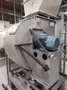
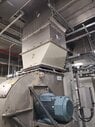
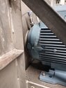
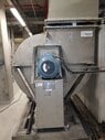
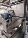
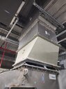
No problem, just trying to understand the arrangement of motor, coupling, shaft, air seal (if any) and bearings.... it's not that easy to show pictures of bearings and couplings since the place has to go in shutdown to turn the fan off. (It runs on 30 Hz now)
If not possible, pictures from different angles around the fan could help us.
It seems to be a cantilever impeller arrangement, which can make vibrations worse.
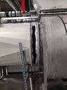
One of your pictures seem to show a solid bridge by-passing the isolation of duct-fan provided by the canvas connection.
Any luck with a video via YouTube?