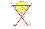
Find Tension in Horizontal Rope DE | Cylinder Mass & Angle θ

Click For Summary
SUMMARY

The discussion focuses on calculating the tension in a horizontal rope (DE) supporting a cylinder of radius R and mass m, positioned between two cross pieces at an angle θ. Participants emphasize the importance of drawing Free Body Diagrams (FBDs) and applying equilibrium equations of statics, specifically $\sum F_x=0$, $\sum F_y=0$, and $\sum T = 0$. The tension T is influenced by the normal forces acting on the cylinder and involves trigonometric functions of half of θ, leading to a complex expression that includes radial forces and gravitational components.

PREREQUISITES
  • Understanding of statics and equilibrium equations
  • Ability to draw and interpret Free Body Diagrams (FBDs)
  • Familiarity with trigonometric functions and their applications in physics
  • Knowledge of forces acting on objects in static equilibrium
NEXT STEPS
  • Study the principles of static equilibrium in mechanics
  • Learn how to effectively draw and analyze Free Body Diagrams (FBDs)
  • Explore the application of trigonometric functions in force calculations
  • Investigate the relationship between normal forces and tension in static systems
USEFUL FOR

Students and professionals in physics, mechanical engineering, and anyone involved in analyzing static systems and forces, particularly those interested in tension calculations and equilibrium analysis.

Ciaran
Messages
71
Reaction score
0
Hi there,

I have a question I'm unable to get properly started on:

A cylinder of radius R and mass m is lodged between cross pieces that make
an angle θ with each other, as shown in the diagram below. The cross pieces
of negligible mass are connected in point C, with lengths AC = BC = 2R and
CD = CE = 3R. Determine the tension in the horizontal rope DE. You may
assume smooth floor.

Any help would be much appreciated!
View attachment 4083
 

Attachments

  • Screen Shot 2015-03-08 at 19.06.54.png
    Screen Shot 2015-03-08 at 19.06.54.png
    4.4 KB · Views: 116
Physics news on Phys.org
Ciaran said:
Hi there,

I have a question I'm unable to get properly started on:

A cylinder of radius R and mass m is lodged between cross pieces that make
an angle θ with each other, as shown in the diagram below. The cross pieces
of negligible mass are connected in point C, with lengths AC = BC = 2R and
CD = CE = 3R. Determine the tension in the horizontal rope DE. You may
assume smooth floor.

Any help would be much appreciated!

Hi Ciaran!

Here's the procedure to tackle any problem in statics.

1. Make an inventory of the external forces.
2. Draw a Free Body Diagram (FBD). That is a diagram of the object with only the external forces.
3. Apply the equilibrium equations of statics: $\sum F_x=0, \sum F_y=0, \sum T = 0$.
4. Make an inventory of the internal forces on each part.
5. Draw an FBD of each part.
6. Apply the equilibrium equations of statics on each part: $\sum F_x=0, \sum F_y=0, \sum T = 0$.

Which external forces can you identify?
Can you already say something about their sizes?
 
Hello again! I know the weight of the system will be the weight of the mass, m and that a reaction force will be split evenly and applied to either bit touching the ground. So it obviously isn't moving in the x or y direction. It's internally, I'm not sure how to deal with the contact forces between the mass and the cross rails.
 
Ciaran said:
Hello again! I know the weight of the system will be the weight of the mass, m and that a reaction force will be split evenly and applied to either bit touching the ground. So it obviously isn't moving in the x or y direction. It's internally, I'm not sure how to deal with the contact forces between the mass and the cross rails.

Good.

Let's give them a name. Let's say G is the force of gravity on the cylinder.
Then at A and B we will have an upward force of G/2 each, yes?
At A and B the horizontal component of force is 0, since the floor gives no friction.
That takes care of steps 1 and 3 and we've been sort of skipping step 2.

Where the rail touches the cylinder, there will be a normal force, perpendicular to the rail.
There won't be friction (parallel to the rail) because the cylinder cannot move/slide along the rail.

If we only look at the cylinder, which forces act on it?
What are their sizes?
 
The only force on the cylinder is G vertically downwards so this must be countered by the two forces from the cross rails, radially?
 
Ciaran said:
The only force on the cylinder is G vertically downwards so this must be countered by the two forces from the cross rails, radially?

Yes. Let's call them N, which is short for normal force.
 
Then the components that are horizontal will provide the tension?
 
Ciaran said:
Then the components that are horizontal will provide the tension?

No, we're not there yet.
The tension force does not work on the cylinder, it works on the rail.
To find the tension, first we need the normal force.

I suggest to try and draw an FBD for the cylinder, and also one for the rail.
We'll need them.
 
My FBD for the cylinder has 3 forces- gravity vertically downwards, and 2 radial forces 'inwards'. And for the rail there are 2 forces, each acting 'outward' due to each side of the rails being pulled down by the mass?
 
  • #10
Ciaran said:
My FBD for the cylinder has 3 forces- gravity vertically downwards, and 2 radial forces 'inwards'.

Good!

And for the rail there are 2 forces, each acting 'outward' due to each side of the rails being pulled down by the mass?

On one rail there is indeed 1 outward acting force by the cylinder.
There are 3 more forces...
 
  • #11
The weight of the rail? But it's considered negligible. And contact forces from where it touches two other rails.
 
  • #12
Ciaran said:
The weight of the rail? But it's considered negligible. And contact forces from where it touches two other rails.

No, not the weight of the rail.

Each rail has 4 forces acting on it:
1. The tension of the rope. Let's call it T.
2. The normal force of the cylinder, which I've already called N.
3. The force of the other rail where it is connected in point C. Let's call it R (for rail).
4. The upward force of the floor, which is G/2, since it's the only external force to counter the weight G of the cylinder.
 
  • #13
I understand that, yes. I'm just not sure about putting it all together. Have you an expression for the tension? I have one but it seems rather complicated and I'm not sure my method was correct. Does the answer involve secant and tangents of half of theta?
 
  • #14
Ciaran said:
I understand that, yes. I'm just not sure about putting it all together. Have you an expression for the tension? I have one but it seems rather complicated and I'm not sure my method was correct. Does the answer involve secant and tangents of half of theta?

Yes, it involves a couple of trigonometric functions of half of theta.
 
  • #15
It's not T= (1/6R)(R_N sec(theta/2))+ (1/3)Gtan(theta/2) is it? Where R_N is the radial force, R the radius of the cylinder and G as discussed before. Apologies for the typing- I'm not exactly an expert in using the software for equations!
 
  • #16
Ciaran said:
It's not T= (1/6R)(R_N sec(theta/2))+ (1/3)Gtan(theta/2) is it? Where R_N is the radial force, R the radius of the cylinder and G as discussed before. Apologies for the typing- I'm not exactly an expert in using the software for equations!

I have something similar but not the same, and in particular I evaluated $R_N$.

As for "using the software for equation", just put a dollar on each side of an equation. That should do the trick.
And if you want to be a bit more fancy, put a backslash (\) in front of some of the symbols like \theta and \tan.
 

Similar threads

  • · Replies 4 ·
Replies
4
Views
2K
  • · Replies 18 ·
Replies
18
Views
2K
Replies
18
Views
2K
  • · Replies 25 ·
Replies
25
Views
3K
  • · Replies 5 ·
Replies
5
Views
3K
  • · Replies 7 ·
Replies
7
Views
2K
Replies
2
Views
2K
  • · Replies 2 ·
Replies
2
Views
2K
  • · Replies 4 ·
Replies
4
Views
3K
  • · Replies 3 ·
Replies
3
Views
14K