Finding torque around a structure

  • Thread starter Thread starter flashskate13
  • Start date Start date
  • Tags Tags
    Structure Torque
Join the discussion
Ask a follow-up here, or get your own question answered by working scientists, mathematicians and engineers — people, not an autocomplete.
Real named experts · corrections over time · the nuance an AI answer skips
2 replies · 2K views
flashskate13
Messages
4
Reaction score
1
Hello All,

I am designing a robot that has these dimensions, I need to work out the torques around T1 to T6, I am unsure of the best way to do it, ie do I do a net torque calculation around the torque to be found or is there a better way.

W1 to W4 =
0.53955 kN​
W5 =
14.44032 kN​
W6 to W9 =
1.0791 kN​
The arms that measure 100mm are currently drawn at 90 degrees but these will probably be more 89 degree.
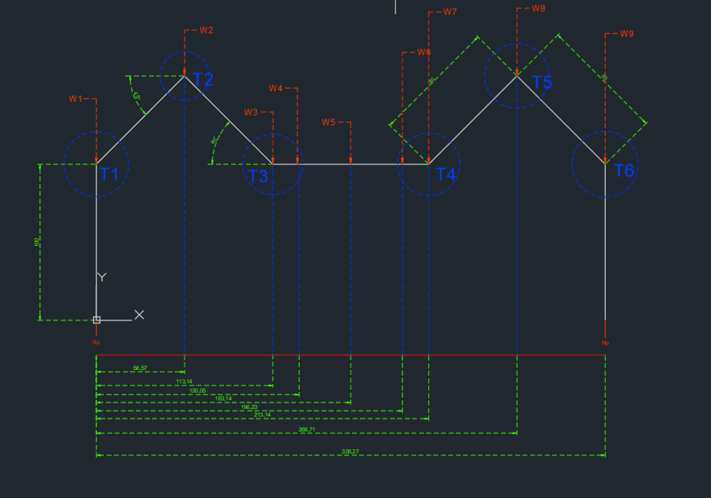
tcals.png


I'm looking at getting the most accurate results this is a new subject to me, and I understand the basics of torque and reactions but don't know how to piece it together for the case.
 
Physics news on Phys.org
It's not clear exactly what you are doing here, but it sort of kinda looks like some sort of series robot. A series robot has a link connected to a joint connected to a link connected to a joint connected ... etc.

Step 1: The general principle is to start at the extreme end, where you have a load. The load has a force due to gravity plus a force due to acceleration. Those forces act through the center of gravity of the load, so are a force plus a moment at the tip of the end link.

Step 2: Move down the end link to the joint. The force and moment due to the load are a force and a (different) moment at the first joint. Added to that is the force and moment due to the mass of the end link. You now have a force and moment at the end joint.

Step 3: Now calculate the force and moment at the next joint. Repeat until you get to the base.

If this is unclear, make a Free Body Diagram (FBD) of the end link alone, post it, and we will help you from there.
 
@jrmichler hope this give you a better idea, so the legs with the red circles on are the ones creating contact withe the ground, at one phase of the robots gait. As you mentioned it is a series of links and connectors.
Now the aim is to find the torque acting at the joints, so I can say this servo would be the ideal choice.
The diagram of previous post is simplified hence why the w1 to w4 number is less than w6 to w9, w1 to w4 represents the single leg
top angle.png