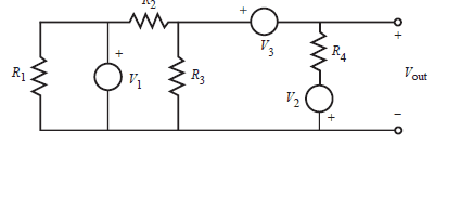
Finding V_out in circuit using mesh analysis

8 replies · 3K views · last reply
charlies1902
Messages
162
Reaction score
0
I attached the circuit. I'm trying to solve for V_out, but I'm stuck.
I can solve for it using mesh analysis, but there must be an easier way. I just don't see it yet. Can anyone give me a hint?
 
Attachments
  • Circuit schematic with resistors R1, R2, R3 and R4, voltage sources V1, V2 and V3, and output terminals labelled Vout with + and − polarity marks.
    Untitled.png
    2.6 KB · Views: 482
Last edited:
charlies1902 said:
I attached the circuit. I'm trying to solve for V_out, but I'm stuck.
I can solve for it using mesh analysis, but there must be an easier way. I just don't see it yet. Can anyone give me a hint?
Circuit schematic with resistors R1, R2, R3 and R4 and voltage sources V1, V2 and V3, with output terminals labelled Vout on the right.

Use Kirchhoff's Laws.

I don't know that it's any easier than mesh analysis.
 
To me simplest seems using the Superposition Theorem.
 
SammyS said:
Circuit schematic with resistors R1, R2, R3 and R4, voltage sources V1, V2 and V3, and output terminals labelled Vout with polarity marked + and −.

Use Kirchhoff's Laws.

I don't know that it's any easier than mesh analysis.

I used mesh analysis. Can someone verify if my answer at the bottom is correct?

Here's what I did using mesh analysis:
1. For the 3 closed loops, assume each loop has a clockwise current
2. I1 is the left loop's current, I2 is the middle, and I3 is the right

Given:
R1=1000Ω R2=2000Ω R3=3000Ω R4=4000Ω
V1=V3=10V, V2=5V

For loop 1 (left):
-1000*I_1-10=0
-1000*I_1=10

For loop 2 (mid):
10-2000I2-3000I2+3000I3=0
-5000I+3000I3=-10

For loop 3:
-3000I3+3000I2-10-4000I3+5=0
3000I2-7000I3=-5


Putting this in matrix form and solving gives:
I1=-0.01A, I2=2.1mA, I3=1.923*10^-4A


Vout-R4*I3+V2=0
Vout=4000*1.923*10^-4 - 5
= -4.2308V

With the way Vout is drawn, it should be negative right?
 
charlies1902 said:
...

With the way Vout is drawn, it should be negative right?
Yes, that's correct.

Notice that you didn't need to consider Loop 1 at all.
 
rollingstein said:
To me simplest seems using the Superposition Theorem.

This was how I did it. Same answer.

Circuit schematic of three rows of resistors and voltage sources, each row ending in a NODE1 label; the top row has R10 1 kΩ, V9 10 V, R11 2 kΩ, R12 3 kΩ and R13 4 kΩ, the middle row has R1 1 kΩ, R3 2 kΩ, R4 3 kΩ, V2 10 V and R5 4 kΩ, and the bottom row has R6 1 kΩ, R7 2 kΩ, R8 3 kΩ, R9 4 kΩ and V5 5 V.
 
If you recognize that R1 is "hidden" from the rest of the circuit by V1 (and so can be eliminated from the circuit entirely), and that V3 forms a supernode of Vout, you can write a single node equation and solve for Vout.

Circuit schematic with resistors R1, R2, R3 and R4, voltage sources V1, V2 and V3, and output terminal Vout; R1 and the V1 branch are circled, with a supernode circled around V3.
 
Attachments
  • Circuit schematic with resistors R1, R2, R3 and R4, voltage sources V1, V2 and V3, and output terminal Vout. A blue loop around R1 is labelled No effect; V1 hides R1, and another loop around V3 is labelled Supernode.
    Fig1.gif
    5.9 KB · Views: 518
Thank you everyone!

The second part of the question asks what the power produced by each voltage source is.
This is easy with the equation P=IV.

The exact wording is "What's the power produced by each source."

Generally speaking, if a current enters the positive terminal of the voltage source that means the power is positive, right?

If a current enters the negative terminal of the voltage source that means the power is negative?

For V_1, the net current enters the negative terminal of V_1.
 
If current exits the + terminal of a voltage source it is producing power (injecting energy into the circuit). If current enters the + terminal it is absorbing power (taking power out of the circuit). Whether you call the power positive or negative depends upon your point of view: are you adding up power being dissipated or power being generated?