Discussion Overview
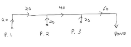
The discussion revolves around the sizing of pumps in a system where three wells each pump 20 gpm to a combined header. Participants explore the appropriate specifications for the pumps considering factors such as head, flow, and system configuration, including the implications of different pump types and real-life applications.
Discussion Character
- Exploratory
- Technical explanation
- Conceptual clarification
- Debate/contested
- Mathematical reasoning
Main Points Raised
- Some participants question the correct way to size the pumps with respect to head and flow, suggesting that all three pumps should have the same specifications.
- Others emphasize the need to consider real-life applications, including actual flow rates, header distances, and head losses.
- A participant proposes applying the Energy Equation from fluid mechanics for incompressible flow to analyze the system.
- There is a discussion about the type of pumps being used, with some assuming submersible centrifugal pumps and others questioning whether they are reciprocating or centrifugal.
- Participants note that each pump will self-adjust its flow based on the resistance or pressure at the discharge point, influenced by head differences, friction in pipes, and back pressure from other pumps.
- One participant suggests estimating discharge pressure for each pump using manufacturer diagrams to determine corresponding flow rates.
- Another participant mentions the importance of understanding the energy equation and continuity in the context of steady, uniform flow of incompressible fluid.
- There is a discussion about the potential for using numerical techniques to solve the system of equations developed from the specified flow rates and head requirements.
Areas of Agreement / Disagreement
Participants express differing views on the approach to sizing the pumps, with no consensus reached on the best method or the specifics of the calculations involved. Some participants agree on the need for a detailed analysis using the Energy Equation, while others focus on practical estimation methods.
Contextual Notes
Limitations include the dependence on assumptions about pump types, flow conditions, and the need for specific variables to be known for accurate calculations. The discussion also highlights the complexity of real-world applications versus theoretical models.
Who May Find This Useful
Individuals interested in fluid mechanics, pump design, and practical applications in engineering and water management may find this discussion relevant.