s32a
- 2
- 2
Hi, my background is in CS and I've no formal physics training. I'd like to check my understanding if anyone's willing. I'm currently messing around with single-fiber reflectance spectroscopy with external illumination as a side project. I'm using an Ocean Optics Red Tide spectrometer paired with a P-400S SMA 400um core fiber. I have two LED arrays covering VIS-NIR, producing two distinct spikes that can be modeled out. My use-case requires compact illumination and halogen bulbs are too bulky; I'm still looking at lenses.
1) For bare fiber, the fiber core diameter is essentially acting as its own aperture, correct?
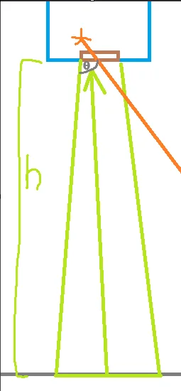
Where anything inside the green cone is within the acceptance angle but something like the orange ray would be too acute and maybe diffuse into the cladding. So to calculate the capture diameter it would essentially be:
D = 2h*tan(θ) +0.04cm where θ is the acceptance half angle?
For example, resulting in an approximate 1.6cm capture diameter at 3.5cm height given a 12.7° half angle. This doesn't guarantee signal, but just defines the boundaries at which light /can/ reflect into the fiber.
2) That assumes the fiber is normal to the surface and so I was trying to figure out how this changes given some measure of angular tilt in order to account for it.
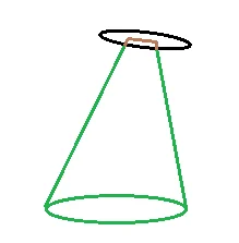
I think I need to consider it as a cone intersecting a plane, but I'm not really sure. If so, using a 3.5cm height again, would it be:
D_1 = D * cos2(θ) / ( cos2(θ) - sin2(ϕ)) = 16.3 cm
D_2 = D * √( sin2(θ) - sin2(ϕ)) / sin(θ) ) = 14.8 cm
where ϕ is the tilt angle (5° here)?
Maybe I can just use a distance sensor array or a gimbal to maintain normality, but I'd like to understand the theory too, please.
1) For bare fiber, the fiber core diameter is essentially acting as its own aperture, correct?
Where anything inside the green cone is within the acceptance angle but something like the orange ray would be too acute and maybe diffuse into the cladding. So to calculate the capture diameter it would essentially be:
D = 2h*tan(θ) +0.04cm where θ is the acceptance half angle?
For example, resulting in an approximate 1.6cm capture diameter at 3.5cm height given a 12.7° half angle. This doesn't guarantee signal, but just defines the boundaries at which light /can/ reflect into the fiber.
2) That assumes the fiber is normal to the surface and so I was trying to figure out how this changes given some measure of angular tilt in order to account for it.
I think I need to consider it as a cone intersecting a plane, but I'm not really sure. If so, using a 3.5cm height again, would it be:
D_1 = D * cos2(θ) / ( cos2(θ) - sin2(ϕ)) = 16.3 cm
D_2 = D * √( sin2(θ) - sin2(ϕ)) / sin(θ) ) = 14.8 cm
where ϕ is the tilt angle (5° here)?
Maybe I can just use a distance sensor array or a gimbal to maintain normality, but I'd like to understand the theory too, please.
Last edited: