Help me breadboard my circuit

  • Thread starter Thread starter bremenfallturm
  • Start date Start date
Click For Summary
SUMMARY

The discussion focuses on the translation of a circuit schematic to stripboard for an Attiny44A microcontroller project involving pushbuttons connected to an ADC pin. The original schematic was incorrect, leading to confusion about the ADC pin's voltage levels. Users suggested using diodes to resolve the issue of the ADC pin being tied to ground. The circuit inspiration came from the book "Practical Electronics For Inventors," specifically referencing a design from Freetronic's Arduino LCD Shield.

PREREQUISITES
  • Understanding of Attiny44A microcontroller functionality
  • Knowledge of ADC (Analog-to-Digital Converter) operation
  • Familiarity with stripboard (Veroboard) circuit design
  • Basic electronics concepts, including capacitor usage
NEXT STEPS
  • Research how to properly implement ADC with multiple input buttons
  • Learn about using diodes in circuit design to prevent voltage conflicts
  • Study capacitor placement and its effects on signal stability
  • Explore advanced techniques for stripboard layout optimization
USEFUL FOR

Electronics hobbyists, microcontroller developers, and anyone involved in circuit design and breadboarding projects.

bremenfallturm
Messages
81
Reaction score
13
TL;DR
I have a question if the schematic-to-stripboard translation of a circuit that I am working on is correct. See below.
Hi.

I am building a project where I have a microcontroller (Attiny44A) connected to some buttons. All the buttons are connected via one ADC pin, and pressing different buttons give different voltages. I have posted topics about this circuit before. I have also successfully breadboarded it, but I now want to transfer it to a piece of stripboard.

This is the basic idea of the circuit - and I have asked a few other questions about this circuit before:
1749143631052.webp

Instead of switches I am using pushbuttons.

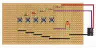
Since I am using the Attiny84A Microcontroller, I will connect "ADC" to the ADC1 input pin. Here is my attempt at stripboarding the whole thing:
1749144023467.webp

where the purple wire indicates the ADC1 input pin. Black and red are of course GND and VCC respectively (note that I abstracted away the input power source in the stripboard design - rest assured I'll connect it)
My basic question is if this is a correct stripboard translation of the schematics?
I guess I also have a bonus question question about the 100nF capacitor
. I've never ever used a capacitor in a circuit and my question is if I got it right or not?

Sorry about having very little electronics experience - but thanks for your help!
 

Attachments

  • 1749143788114.webp
    1749143788114.webp
    31.2 KB · Views: 21
Engineering news on Phys.org
bremenfallturm said:
TL;DR Summary: I have a question if the schematic-to-stripboard translation of a circuit that I am working on is correct. See below.

My basic question is if this is a correct stripboard translation of the schematics?
It's pointless to ask since the schematic is wrong. How do you expect the ADC pin to have anything except 0 volts on it no matter which pushbutton/switch is pressed?
 
  • Like
Likes   Reactions: davenn and berkeman
Agreed. Where did you get this schematic from? Can you upload an image of that original circuit and say what you need to do to fix your schematic? Thanks.
 
Apart from things already mentioned: unless you had cut the strips μC legs are connected in pairs.
 
  • Like
Likes   Reactions: davenn
Averagesupernova said:
How do you expect the ADC pin to have anything except 0 volts on it no matter which pushbutton/switch is pressed?
You might investigate how some diodes might solve your problem instead of connect all the outputs to ground.
You've actually got yourself a crude DAC here (once it's working).
 
sophiecentaur said:
You might investigate how some diodes might solve your problem instead of connect all the outputs to ground.
You've actually got yourself a crude DAC here (once it's working).
It's not my problem. I simply pointed out to the OP that the ADC pin will always be at zero volts. It is tied to ground. I'm pretty sure the OP knows he has a crude A/D converter, or that is the goal at least. We haven't gotten a reply from the OP so I'm not losing any sleep over it.
 
Averagesupernova said:
It's pointless to ask since the schematic is wrong. How do you expect the ADC pin to have anything except 0 volts on it no matter which pushbutton/switch is pressed?

berkeman said:
Agreed. Where did you get this schematic from? Can you upload an image of that original circuit and say what you need to do to fix your schematic? Thanks.

Averagesupernova said:
the ADC pin will always be at zero volts. It is tied to ground.
Mhrm, oops. Sorry... I drew the schematics wrong - this is what I intended to show you
1749720837263.webp

Where the circuit comes from:
I was inspired by the circuit below, which is presented in the book Practical Electronics For Inventors, p. 875.
The book says that the circuit diagram is from Freetronic's Arduino LCD Shield, and indeed it is, I found the circuit image here https://www.freetronics.com.au/pages/16x2-lcd-shield-quickstart-guide.
1749718393247.webp

Now I was simply trying to add a small capacitor at the ADC pin to make the detection more stable. I am not using an Arduino, rather an Attiny84A.
So basically, without the capacitor, this is the circuit

1749720878304.webp

I breadboarded the circuit (the title was supposed to say "Help me stripboard my circuit", not "Help me breadboard my circuit", sorry!). When I did this, I connected the capacitor as follows, if this makes any sense at all:
1749721070251.webp

And this seems to work, I get different voltage level readings off that ADC pin.
 
bremenfallturm said:
I breadboarded the circuit (the title was supposed to say "Help me stripboard my circuit", not "Help me breadboard my circuit", sorry!)
I changed your title to use the more standard term "breadboard". I've never heard the term "stripboard" before.
 
  • #10
Baluncore said:

Ah, that may be why I've never heard of it... :wink:
It is commonly also known by the name of the original product Veroboard, which is a trademark, in the UK, of British company Vero Technologies Ltd and Canadian company Pixel Print Ltd.
 
  • #11
Averagesupernova said:
It's not my problem.
Sorry. I meant "to whom it may concern."
 
  • Like
Likes   Reactions: weirdoguy

Similar threads

  • · Replies 9 ·
Replies
9
Views
2K
  • · Replies 14 ·
Replies
14
Views
2K
  • · Replies 3 ·
Replies
3
Views
2K
  • · Replies 4 ·
Replies
4
Views
1K
  • · Replies 1 ·
Replies
1
Views
2K
Replies
12
Views
2K
  • · Replies 6 ·
Replies
6
Views
2K
  • · Replies 19 ·
Replies
19
Views
3K
  • · Replies 9 ·
Replies
9
Views
4K
  • · Replies 1 ·
Replies
1
Views
5K