Hi, has anybody had trouble building the ELENCO 108 AM/FM RADIO KIT

  • Thread starter Thread starter michael1978
  • Start date Start date
  • Tags Tags
    Building Hi Radio
Click For Summary

Discussion Overview

The discussion revolves around troubleshooting issues encountered while building the ELENCO 108 AM/FM Radio Kit. Participants share their experiences, measurements, and suggestions related to the assembly and functionality of the radio, focusing on both AM and FM reception problems.

Discussion Character

  • Technical explanation
  • Debate/contested
  • Experimental/applied

Main Points Raised

  • One participant reports hearing only high noise when switching to AM or FM after following the assembly instructions and testing with a multimeter.
  • Another participant shares their experience of swapping the battery and speaker, suggesting that the original poster provide more detailed information, including a schematic and measured DC voltages.
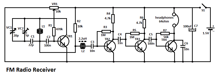
  • Measurements of various test points (TP) are provided by a participant, indicating different voltage readings for AM and FM modes, but the problem persists even after trying a different speaker.
  • There is a request for the original poster to upload a marked schematic with measured voltages to assist in diagnosing the issue.
  • Discussion includes the suggestion to check for an alignment procedure in the kit's instructions and whether it was assembled from a kit with a printed circuit board.
  • Another participant notes that TP17 is Ground and requests voltage measurements relative to this point for further analysis.
  • One participant mentions using an LM386 instead of a transistor amplifier, prompting requests for the schematic and test point voltages.
  • A later reply suggests replacing the battery based on voltage measurements that are slightly below the expected level.

Areas of Agreement / Disagreement

Participants express various troubleshooting approaches and share differing experiences, indicating that multiple competing views remain regarding the cause of the issues with the radio kit. The discussion does not reach a consensus on the solution.

Contextual Notes

Participants highlight the importance of specific measurements and schematic details, indicating that the discussion is dependent on these factors for further troubleshooting. There are unresolved aspects regarding the alignment procedure and the specific components used in the assembly.

michael1978
Messages
434
Reaction score
19
Hello, i build the radio like they say in the book, and i did everything with VOM(testing with only multimeter),
everything was like in book , but when i finish, i switch to am or fm, i just hear high noise
:doh:
 
Engineering news on Phys.org
When I built it, I accidentally got the battery and the speaker swapped. It took me a while to figure out my mistake. o0)

But seriously, how are we supposed to help you with so little information? Post the schematic and label it with the DC voltages you measure in your circuit -- that will give us a starting point to try to help you...
 
berkeman said:
When I built it, I accidentally got the battery and the speaker swapped. It took me a while to figure out my mistake. o0)

But seriously, how are we supposed to help you with so little information? Post the schematic and label it with the DC voltages you measure in your circuit -- that will give us a starting point to try to help you...
You had the same, i can tell you the value, you mean the TEST POINT(TP)? i don't know, which value you are interessed? just tell me and i will do it
 
michael1978 said:
You had the same, i can tell you the value, you mean the TEST POINT(TP)? i don't know, which value you are interessed? just tell me and i will do it
I was kidding in my first paragraph, making fun of the fact that you posted with so little information and wanted help. Sorry if my humor wasn't obvious.

In my second paragraph, I asked you to Upload a copy of the schematic (as a PDF or JPEG file), and be sure to mark the DC voltages you measure at each node of the circuit on the schematic. That will help us to look for obvious problems (like if you measure a zero voltage at a place in the circuit where the voltage should be non-zero). Mark up the voltage you measure on the schematic that you have, and use the UPLOAD button to Upload a PDF or JPEG copy of that marked-up schematic. Here is an example without the measured voltages marked on it yet...

http://electroschematics.com/wp-content/uploads/2010/07/fm-radio-receiver.gif
fm-radio-receiver.gif
 
berkeman said:
When I built it, I accidentally got the battery and the speaker swapped. It took me a while to figure out my mistake. o0)

But seriously, how are we supposed to help you with so little information? Post the schematic and label it with the DC voltages you measure in your circuit -- that will give us a starting point to try to help you...
I Measure, Test Point, without connection a speaker(because i thought the speaker was bad, so i desoldeer, and i connect with wire other speaker 8ohm but the same problem stays),
so
i switch to FM
tp15 and tp2=2.74V
tp15 and tp13=1.4V
tp15 and tp11=6.59V
tp15 and tp10=1.20V
tp15 and tp9=7.08V
tp15 and tp8=6.43V
tp15 and tp12=6.74V
i switch to am
tp15 and tp2=0.02V
tp15 and tp3=7.77V
tp15 and tp1=4.21V
tp15 and tp4=8.13V
tp15 and tp5=1.34V
tp15 and tp6=0V
tp15 and tp14'=0.02V
TP15=GND
 
michael1978 said:
I Measure, Test Point, without connection a speaker(because i thought the speaker was bad, so i desoldeer, and i connect with wire other speaker 8ohm but the same problem stays),
so
i switch to FM
tp15 and tp2=2.74V
tp15 and tp13=1.4V
tp15 and tp11=6.59V
tp15 and tp10=1.20V
tp15 and tp9=7.08V
tp15 and tp8=6.43V
tp15 and tp12=6.74V
i switch to am
tp15 and tp2=0.02V
tp15 and tp3=7.77V
tp15 and tp1=4.21V
tp15 and tp4=8.13V
tp15 and tp5=1.34V
tp15 and tp6=0V
tp15 and tp14'=0.02V
TP15=GND
Please upload the schematic or link to a copy of it on the Internet. Thank you.
 
berkeman said:
Please upload the schematic or link to a copy of it on the Internet. Thank you.
 

Attachments

berkeman said:
I was kidding in my first paragraph, making fun of the fact that you posted with so little information and wanted help. Sorry if my humor wasn't obvious.

In my second paragraph, I asked you to Upload a copy of the schematic (as a PDF or JPEG file), and be sure to mark the DC voltages you measure at each node of the circuit on the schematic. That will help us to look for obvious problems (like if you measure a zero voltage at a place in the circuit where the voltage should be non-zero). Mark up the voltage you measure on the schematic that you have, and use the UPLOAD button to Upload a PDF or JPEG copy of that marked-up schematic. Here is an example without the measured voltages marked on it yet...

http://electroschematics.com/wp-content/uploads/2010/07/fm-radio-receiver.gif
fm-radio-receiver.gif
i post schematic
 
  • #10
michael1978 said:
i post schematic
Thank you, that helps a lot. I think I'll move this thread to the EE forum, to get more specialized help.

It looks like there are several adjustable components in the schematic. Was there an "alignment procedure" included in the instructions? Also, did you assemble this from a kit with a PC board included?
 
  • #11
michael1978 said:
I Measure, Test Point, without connection a speaker(because i thought the speaker was bad, so i desoldeer, and i connect with wire other speaker 8ohm but the same problem stays),
so
i switch to FM
tp15 and tp2=2.74V
tp15 and tp13=1.4V
tp15 and tp11=6.59V
tp15 and tp10=1.20V
tp15 and tp9=7.08V
tp15 and tp8=6.43V
tp15 and tp12=6.74V
i switch to am
tp15 and tp2=0.02V
tp15 and tp3=7.77V
tp15 and tp1=4.21V
tp15 and tp4=8.13V
tp15 and tp5=1.34V
tp15 and tp6=0V
tp15 and tp14'=0.02V
TP15=GND
It looks like TP17 (lower right of the schematic) is Ground. Can you please measure the voltages of the other test points with respect to TP17 Ground? That would be helpful. Just keep you meter's negative test lead on TP17, and measure the voltages of the other test points with your meter's positive lead. Thank you.
 
  • #12
berkeman said:
It looks like TP17 (lower right of the schematic) is Ground. Can you please measure the voltages of the other test points with respect to TP17 Ground? That would be helpful. Just keep you meter's negative test lead on TP17, and measure the voltages of the other test points with your meter's positive lead. Thank you.
I don't use transistor amplifier, but i use lm386,
 
  • #13
michael1978 said:
I don't use transistor amplifier, but i use lm386,
Please post the schematic for what you have built, and post the test point voltages. Thank you.
 
  • #14
berkeman said:
Please post the schematic for what you have built, and post the test point voltages. Thank you.
I show you tomorow maybe, because i go to sleep, here is 24:10 goodnight berkeman
 
  • Like
Likes   Reactions: berkeman
  • #15
berkeman said:
It looks like TP17 (lower right of the schematic) is Ground.
TP15 is also GND; that's below Q5 in the FM section.

@michael1978
I have only looked at the AM section because that part is easier. Let's get that and the earphone working first.
Page 34 of the manual says the battery should measure 8.5V or more with the power switch turned on. Your measurements show around 7.8V to 8.1V. Please replace the battery.

This test can be done with the old battery. It will give you something to do until you get a new one.
There is a problem at TP6, it reads 0V but should be about 8V or higher (about the same voltage as at TP4).
Check the wiring at the primary (left) side of T6, around L5 and around Q7. There is probably a bad or missing connection to T6.

Let us know what you find.

Cheers,
Tom
 
  • #16
Tom.G said:
TP15 is also GND; that's below Q5 in the FM section.

@michael1978
I have only looked at the AM section because that part is easier. Let's get that and the earphone working first.
Page 34 of the manual says the battery should measure 8.5V or more with the power switch turned on. Your measurements show around 7.8V to 8.1V. Please replace the battery.

This test can be done with the old battery. It will give you something to do until you get a new one.
There is a problem at TP6, it reads 0V but should be about 8V or higher (about the same voltage as at TP4).
Check the wiring at the primary (left) side of T6, around L5 and around Q7. There is probably a bad or missing connection to T6.

Let us know what you find.

Cheers,
Tom
GoodMorning, i was wrong, because now between T6 is 8.7V, now is not anymore so high noise, but low noise, and when i rotate the VARcapacitor
i don't hear nothing changes, i can't pickup any fm or am radio station?
what do you think where is problem?
have a nice day
 
  • #17
berkeman said:
Thank you, that helps a lot. I think I'll move this thread to the EE forum, to get more specialized help.

It looks like there are several adjustable components in the schematic. Was there an "alignment procedure" included in the instructions? Also, did you assemble this from a kit with a PC board included?
yes
 
  • #18
Tom.G said:
TP15 is also GND; that's below Q5 in the FM section.

@michael1978
I have only looked at the AM section because that part is easier. Let's get that and the earphone working first.
Page 34 of the manual says the battery should measure 8.5V or more with the power switch turned on. Your measurements show around 7.8V to 8.1V. Please replace the battery.

This test can be done with the old battery. It will give you something to do until you get a new one.
There is a problem at TP6, it reads 0V but should be about 8V or higher (about the same voltage as at TP4).
Check the wiring at the primary (left) side of T6, around L5 and around Q7. There is probably a bad or missing connection to T6.

Let us know what you find.

Cheers,
Tom
I see one video, all collector of fm have the same value, he show in the video and i tested my the same they have,
but like in am and fm sometimes is high noise, sometime little bit noise, but i can't catch any signal,
 
  • #19
now is low NOISE like in am or fm but i can get any signal, what do you think , where is problem:bow:
 
  • #20
Does anything you do make a change in the high noise or low noise?
If yes, tell use what you do to make that change.
 
  • #21
Tom.G said:
Does anything you do make a change in the high noise or low noise?
If yes, tell use what you do to make that change.
I think maybe, i soldeer it one more lm386 WITH bypass capacitor at pin 2 and 6, and also i change the battery little bit old,
and also i can hear nothing from earphony, totally nothing,
 
  • #22
michael1978 said:
WITH bypass capacitor at pin 2 and 6
That should be pin 4 and 6.

Do you have any test equipment besides the voltmeter?
 
  • #23
Tom.G said:
That should be pin 4 and 6.

Do you have any test equipment besides the voltmeter?
how not, how i measure til now?, but in the book is between pin 2 and 6 capacitor, how come now pin 4 and 6(are you sure)?
 
  • #24
michael1978 said:
how not, how i measure til now?, but in the book is between pin 2 and 6 capacitor, how come now pin 4 and 6(are you sure)?
i have dvm
 
  • #25
michael1978 said:
how not, how i measure til now?, but in the book is pin 2 and 6, how come now pin 4 and 6(are you sure)?
The image below is from the datasheet for the LM386 made by National Semiconductor. As you can see, the supply voltage is on pin 6, Ground is pin 4, and -Input is pin 2. Your circuit has pin 2 connected to Ground, probably as a short circuit trace between pins 2 and 4. I said pin 4 for the bypass capacitor just to be very safe (conservative). If there is a bad connection on the board between pins 2 and 4, the bypass might not connect to Ground if soldered to pin 2.

If the connection between pins 2 and 4 are good, for your circuit it probably will not make much difference. For other circuits it can make a difference, so we all get in the habit of connecting bypass capacitors to the power and Ground pins just to avoid problems.

OK, you have DVM. What make and model is it?

upload_2018-7-15_15-14-38.png
 

Attachments

  • upload_2018-7-15_15-14-38.png
    upload_2018-7-15_15-14-38.png
    8.5 KB · Views: 1,099
  • #26
Tom.G said:
The image below is from the datasheet for the LM386 made by National Semiconductor. As you can see, the supply voltage is on pin 6, Ground is pin 4, and -Input is pin 2. Your circuit has pin 2 connected to Ground, probably as a short circuit trace between pins 2 and 4. I said pin 4 for the bypass capacitor just to be very safe (conservative). If there is a bad connection on the board between pins 2 and 4, the bypass might not connect to Ground if soldered to pin 2.

If the connection between pins 2 and 4 are good, for your circuit it probably will not make much difference. For other circuits it can make a difference, so we all get in the habit of connecting bypass capacitors to the power and Ground pins just to avoid problems.

OK, you have DVM. What make and model is it?

View attachment 228076
Thnx man i go to change, and i will let you know, i will let you know direct
 
  • #27
michael1978 said:
Thnx man i go to change, and i will let you know, i will let you know direct
I have DVM9915, i soldeer it, now the earphone is working i hear noise but i don't get SIGNAL:cry:
 
  • #28
Does anything you do make a change in the high noise or low noise?
If yes, tell use what you do to make it change.
Does it just get louder and softer or does it sound different?
 
  • #29
Tom.G said:
Does anything you do make a change in the high noise or low noise?
If yes, tell use what you do to make it change.
Does it just get louder and softer or does it sound different?
the earphone is working, and i have a little bit louder, but not like in begin
 
  • #30
Does the sound change when you turn down the volume control?
How does it change?
 

Similar threads

Replies
20
Views
2K
  • · Replies 4 ·
Replies
4
Views
5K
  • · Replies 1 ·
Replies
1
Views
10K
  • · Replies 24 ·
Replies
24
Views
4K
  • · Replies 17 ·
Replies
17
Views
7K
Replies
17
Views
6K
  • · Replies 5 ·
Replies
5
Views
4K
Replies
3
Views
17K
  • · Replies 11 ·
Replies
11
Views
3K
Replies
4
Views
3K