How Can I Design an Underdamped RLC Resonator Below 3kHz?

Join the discussion
Registration is free. Start your own thread to ask a follow-up.
7 replies · 3K views
swraman
Messages
165
Reaction score
0
Hi,

I thought this would be a simple project but I have not been able to get this to work.

I need to design a circuit that exhibits a resonance below 3kHz. It must be underdamped, and the drive current limited to ~5mA.

I was usign this as an inductor:
http://en.wikipedia.org/wiki/Gyrator
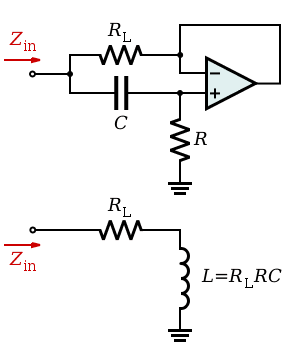
300px-Op-Amp_Gyrator.svg.png


At the bottom, which simulates the inductor.

My values I am using are:
RL=1kOhm
C = .1uF
R = 10kOhm

these lead to a simulated L=.9

Combining this with a .01uF capacitor, I should get a resonance at about 1000rad/sec, and if I measure the voltage across the capacitor I should see a peak gain of 9.5 (determined analytically using Matlab). But when I put in a broadband random signal into the system, I see nothing when I measure the voltage across the capacitor but it looks exactly like my input broadband signal.

Is there something I am missing?
 
Engineering news on Phys.org
Have you breadboarded something or is this based on a simulation?

In case of simulation, could you show the details of it, schematic, output waveforms etc.?
 
Breadboard. I am using a FFT data acquisition system which measures input and output and calculates a transfer function.

I used simple KVL analysis to generate transfer functions and plot the expected FRF's in Matlab, which gave me the expected peak/resonance. I am using 2 9V batteries (one in negative direction) to power the op amp. I know the op amp works because I can make other circuits with t which operate fine.
 
Could do with a schematic of your test setup, including how your instruments are hooked up (and their make and model).
 
http://www.ocf.berkeley.edu/~sraman/dp/image_circuit.jpg

I am using an NTE941M op amp:
http://www.nteinc.com/specs/900to999/pdf/nte941m.pdf

My V+ and V- terminals are plugged into +/-9V batteries (reverse polarity to get -9V).

http://www.ocf.berkeley.edu/~sraman/dp/board.jpg

I have not shown the 9V batteries plugged in, they attach to terminals 4 and 7 as shown on the datasheet.

My instruments I am using are (I am fairly certain) not the issue. It is a FFT Analyzer by Data Physics Corp. I am using a broadband random generator and measuring the response around the first .01uF capacitor. All are grounded to the breadboards ground and I am making a differential measurement across the capacitor when measuring its response.

Thanks

Raman
 
Last edited by a moderator:
It appears that the RL part of the circuit is working properly...With a broadband random input I get the following output spectrum:

http://www.ocf.berkeley.edu/~sraman/dp/response_r.jpg

Which seems accurate, rolloff around 150Hz. But when I add the capacitor in front of the circuit, I get the following (measuring response across series capacitor), with a possible resonance at 1000hz instead of ~150:
http://www.ocf.berkeley.edu/~sraman/dp/response_c.jpg
 
Last edited by a moderator:
The thing is, in this:
300px-Op-Amp_Gyrator.svg.png


The bottom circuit is only equivalent (approximately) to the top one when R >> R_L.

I assume you got L = 0.9 H from something like:
Z_in = (R_L + j*omega*R_L*R*C) || (R + 1/(j*omega*C) = (1.000e3 + j*0.9000) Ω

for R_L = 1 kΩ, R = 10 kΩ, C = 100 nF, omega = 1 rad/s.

For omega = 10e3 rad/s:
Z_in = (5.500e3 + j*4.500e3) Ω

thus not the impedance you would expect for the circuit in the bottom.

Adjusting the values of the resistors to be more in line with R >> R_L:
Z_in = (1.089e3 + j*9.891e3) Ω

for R_L = 100 Ω, R = 100 kΩ, C = 100 nF, omega = 10e3 rad/s,

which is much more like it should be according to the equivalent circuit in the bottom.

In short, try R1 = 100 Ω, R2 = 100 kΩ instead. I'd expect a resonance frequency of around 1/(2*pi*sqrt(1 H*10e-9 F) ~= 1.6 kHz with a gain of around 20 dB (you're limited by your rails though).
 
Last edited:
Thanks. I knew there must have been some condition I was overlooking for the simulated inductor to work.

I did the best I could with the pieces I have, and used a 250Ohm resistor instead of 100 that you suggest. The response is starting to look much better.
http://www.ocf.berkeley.edu/~sraman/dp/response_c_250ohm.jpg

I don't quite understand why the response levels out at ~3kHz but I am not really concerned with any poles/zeros after the resonance.

I will but the necessary components tomorrow. Thanks for all the help, Ill let you know how it works.
 
Last edited by a moderator: