Properly producing TDR on PNA network analyzer N5224B

  • Thread starter Thread starter yefj
  • Start date Start date
yefj
Messages
75
Reaction score
2
Hello, my pna port1 is connected to a resonator.
the resonator is connected to pna threw a good line 30cm long.
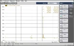
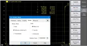
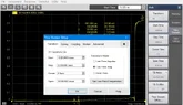
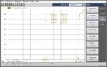
I made S11 of 10Mhz to 40Ghz and converted to time domain(probably pna doing ifft) as you can see in the photos.
the time resopnce is very bad.
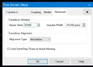
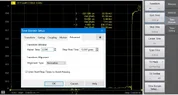
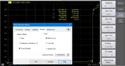
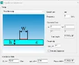
There is a menu I have to the time domain shownin the photo.
What setting could make my TDR better looking so I could see the reflections from the load of port 1 ?

Capture2.webp


time domain window_s11 (1).webp
 
Last edited by a moderator:
Engineering news on Phys.org
If you are measuring S11, why are connecting another coax cable to the 2nd VNA port? For S11 you should only need one connection to the resonator. You can just terminate the output of the resonator in a 50 Ohm coax terminator.

What frequency is the resonator tuned to? Can you show S11 in the frequency domain for reference? How does that measurement change if you connect the resonator directly to Port 1 of the VNA with just a coax adapter instead of through a 30cm coax cable?

(Very nice instrument, BTW.) :smile:
 
yefj said:
What setting could make my TDR better looking so I could see the reflections from the load of port 1 ?
Since it is computing the time domain from the frequency domain, it might have 'automatic fixture removal' software running that will remove the connection cables from the frequency domain network analysis. That would remove the cables from your computed TDR.
 

Similar threads

  • · Replies 17 ·
Replies
17
Views
1K
  • · Replies 6 ·
Replies
6
Views
8K
  • · Replies 2 ·
Replies
2
Views
2K