How Does V-Belt Tension Arise in a Free Body Diagram?

  • Thread starter Thread starter etotheipi
  • Start date Start date
  • Tags Tags
    Belt Fbd
Join the discussion
Ask a follow-up here, or get your own question answered by working scientists, mathematicians and engineers — people, not an autocomplete.
Real named experts · corrections over time · the nuance an AI answer skips
7 replies · 3K views
etotheipi
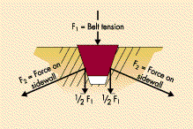
I found this diagram,
1590221457366.png


How does the belt tension arise? I would assume it be exerted by belt elements on either side (i.e. unbalanced tension forces due to curvature around the pulley), but that's not clear from this diagram.

Also, just to make sure I'm not going crazy, why have they drawn two forces of ##\frac{1}{2}\mathbf{F}_1## on here? I'm pretty sure they're intended to be vector components of the force ##\mathbf{F}_2## on the walls due to the belt, but if so then it's not really that clear :confused:. Thank you!
 
Last edited by a moderator:
Physics news on Phys.org
Hi,
A sideways view would reveal tension along the heart line of the belt, as you expect. Most of it is pulling the belt into the groove.
You're not going crazy (at least not in this matter :smile: ). The two ##{1\over 2}{\bf F}_1## is what the belt exerts on the pulley.
In that respect this is an (incomplete) FBD of the pulley, not of the belt.
 
  • Like
Likes   Reactions: etotheipi
BvU said:
The two ##{1\over 2}{\bf F}_1## is what the belt exerts on the pulley.
In that respect this is an (incomplete) FBD of the pulley, not of the belt.

Ah okay awesome. `I just wondered since I think it would be clearer to draw the two ##\frac{1}{2}\mathbf{F}_1##'s with dotted lines instead of solid lines, since that diagram is double counting the vertical component of the reaction force.

Thank you!
 
There will be a context for this diagram. That may say "this diagram shows how the belt tension is propagated to the pulley", as opposed to the incorrect "this is an FBD of the belt" -- because then reversing the two ##{1\over2}1{\bf F}_1## and ##{\bf F}_2## would be better, but then the diagram becomes cluttered and unclear.
 
  • Like
Likes   Reactions: etotheipi
BvU said:
There will be a context for this diagram. It's not 100% corerct for sure. Reversing the two ##\frac{1}{2}\mathbf{F}_1## and ##\mathbf{F}_2## would be better, but then the diagram becomes cluttered and unclear.

I would get rid of the ##\frac{1}{2}\mathbf{F}_1## arrows entirely.
 
  • Skeptical
Likes   Reactions: BvU
@BvU I would draw a diagram like this, where the 3 inner forces act on the V belt and the two outer ones act on the groove/pulley:

1590231670715.png

Whilst we could also add components in, I would make sure to distinguish them clearly:

1590231814746.png


My opposition to the presence of the two ##\frac{1}{2}\mathbf{F}_1## arrows is because one might then be inclined to believe erroneously that it is a separate force acting on the V belt, as opposed to a vertical component of an existing force on the diagram.
 
  • Like
Likes   Reactions: Lnewqban