How to get to this KVL expression

  • Thread starter Thread starter nhrock3
  • Start date Start date
  • Tags Tags
    Expression Kvl
Join the discussion
Ask a follow-up here, or get your own question answered by working scientists, mathematicians and engineers — people, not an autocomplete.
Real named experts · corrections over time · the nuance an AI answer skips
9 replies · 4K views
nhrock3
Messages
403
Reaction score
0
in this photo there is the circuit and the KVL of the solution
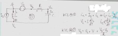
5aov46.jpg


but when i tried to do the KVL
i go from the arc(3 lines represents potential zero)
in counter clockwise direction
so i get[tex]V_L + V_C+V_R-V_s=0[/tex]
when i go against the direction of a current the voltage is on PLUS
when in the voltage source i go from + to - we have -V_s

so where is my mistake
i can't figure out how to get to the expression they got from my expression
?
 
Last edited:
Physics news on Phys.org
Are you saying that the KVL equation you have drawn in that picture is the solution you should arrive to? The equation looks incorrect as the last term is in units of current, not voltage. The summation of voltages should never equal units of current.

The solution aside I would recommend you look at what you are defining as VL, and VC. These values are just assigned to particular nodes in the circuit. They don't describe the voltage drop across elements.

See this circuit below for the difference. It's not the node voltage at the "+" end of the capacitor that's important, it's the voltage at the "+" end of the capacitor relative to the "-" end of the capacitor. Same applies for the inductor and the resistor.

http://img6.imageshack.us/img6/7553/0210001730.jpg"
 
Last edited by a moderator:
yes you are correct its current not a voltagedoes my logic in finding the KVL correct?
 
Last edited:
nhrock3 said:
what do you mean "as the last term is in units of current, not voltage"
the last is just VS its not a curent

Sorry for any confusion, I was referring to the KVL equation in the image you posted. The equation reads:

[tex]V_S=V_L+V+\frac{V_S-V_C}{R}[/tex]​

V/R gives a current, that's all I was saying.
 
nhrock3 said:
does my logic in finding the KVL correct?

No the logic you have used in finding the equation, [tex]V_L+V_C+V_R-V_S=0[/tex] is incorrect.


The voltage V_c does not represent the voltage drop across the resistor that is needed for the KVL loop. It is the voltage at that node relative to ground. So it is the voltage across the resistor plus the voltage supplied by the voltage source.

Take a look at the image I linked to earlier. The voltages in that image are the voltages across each circuit element rather then the voltage at a particular node relative to ground. Do a KVL loop of that circuit and substitute the values of each voltage with the corresponding equation I listed with the image. Your KVL equation should give you a second order differential equation in terms of I_L and I_c. Use the KCL equation you showed in your image in the OP and you can get the differential equation in terms of either I_L or I_c with respect to V_S and I_S.
 
"V_c does not represent the voltage drop across the resistor"

V_c represents the drop accros the capacitor

V_r represent the voltage drop across the resistor
 
In your drawing the node V_c is labeled as a the voltage level at a particular node. With the location of the ground in your circuit one would assume that unreferenced node voltages are referenced to ground. This would make V_c the voltage drop across the resistor and the voltage source, not the capacitor even though that's what you really want V_c to be. Look how the circuit I drew is different.
 
"V_c is the voltage across the resistor plus the voltage supplied by the voltage source"
i agree.
so what is the correct KVL?
 
what is the correct KVL equation you think?
 
anyone??
i can't understand what is the right kvl
?