- 7,719
- 3,856
- TL;DR
- Post your petrographic images!
Sometimes I win at eBay:

On the right is a Ehringhaus quartz compensator in perfect condition- I believe the seller didn't know what they had, I got it for $200. Now I need to learn how to use it :)
It seems that whatever I decide to learn how to photograph, @davenn has been there already. With his encouragement, I am getting some thin sections fabricated, hopefully I'll have them by this summer. In the meantime, I scored a set of fossil thin sections (at about $5 per section), my suspicion is that they were made by a (grad?) student as part of a course.
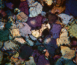
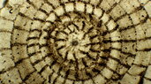
Here's a macro-view, taken with a zoom Luminar, of a sample from the Graford Formation (Upper Pennsylvanian) show some fossils in cross-section:

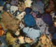
And a closer view at 4X:

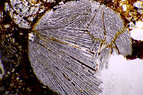
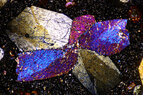
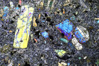
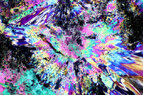
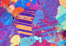
One thing I don't understand are the presence of small flakes of "something", I think part of the sample prep- these are uncovered and non polished sections. The flakes are uniform size, square, and highly birefringent. Two views, one with parallel polarizers and the other with crossed polars:


continued....
On the right is a Ehringhaus quartz compensator in perfect condition- I believe the seller didn't know what they had, I got it for $200. Now I need to learn how to use it :)
It seems that whatever I decide to learn how to photograph, @davenn has been there already. With his encouragement, I am getting some thin sections fabricated, hopefully I'll have them by this summer. In the meantime, I scored a set of fossil thin sections (at about $5 per section), my suspicion is that they were made by a (grad?) student as part of a course.
Here's a macro-view, taken with a zoom Luminar, of a sample from the Graford Formation (Upper Pennsylvanian) show some fossils in cross-section:
And a closer view at 4X:
One thing I don't understand are the presence of small flakes of "something", I think part of the sample prep- these are uncovered and non polished sections. The flakes are uniform size, square, and highly birefringent. Two views, one with parallel polarizers and the other with crossed polars:
continued....