AntonAv
- 1
- 0
Thread moved from the technical forums to the schoolwork forums
TL;DR Summary: How to calculate induction heat flux (density) induced by an infinitely long wire in an infinitely large slab.
Hi,
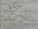
I have to simulate induction heating caused by a straight long wire in a thick slab of material (no strict limitations).
To make it, in the best case I should calculate heat flux density. The heat source is a Joule heating in a slab. This way the task concludes in finding induced currents.
I have attached on the foto below task description and two approaches to solve it.
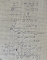
In the first approach I am calculating induced currents from H-field circulation. I am not sure in this solution as a limitation in EM field penetration depth is not occurred, and I am not really experienced in electromagnetic engineering.
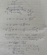
The second approach is based on a 2D model and aimed to find linear density of EDF. I am also not sure in it. Especially I have doubts that integral for EDF is divergent without limitations.
I want you to check my solutions, please!
May be you have another approaches to solve it, they are super welcome!
Best wishes for you!!!
Images consist of 3 Pages.
1. Task description. 2. First approach to solve. 3. Second approach to solve
Hi,
I have to simulate induction heating caused by a straight long wire in a thick slab of material (no strict limitations).
To make it, in the best case I should calculate heat flux density. The heat source is a Joule heating in a slab. This way the task concludes in finding induced currents.
I have attached on the foto below task description and two approaches to solve it.
In the first approach I am calculating induced currents from H-field circulation. I am not sure in this solution as a limitation in EM field penetration depth is not occurred, and I am not really experienced in electromagnetic engineering.
The second approach is based on a 2D model and aimed to find linear density of EDF. I am also not sure in it. Especially I have doubts that integral for EDF is divergent without limitations.
I want you to check my solutions, please!
May be you have another approaches to solve it, they are super welcome!
Best wishes for you!!!
Images consist of 3 Pages.
1. Task description. 2. First approach to solve. 3. Second approach to solve