Inductive heating and eddy currents

In summary, the individual is working on a project that uses inductive heating and has some questions around the magnetic fields and localized eddy currents. They ask about iron core vs. air core coils, the weight of the lead slug, and the depth of heating. They also ask about controlling the magnetic field.
  • #1
MagneticMagic
25
2
TL;DR Summary
Magnetics and eddy currents, different design for specific use.
Quick question 1st, is there a Magnetics forum here on PF?

I am working on a project that is inductive heating using two coils and some simplified current control circuitry that can drive coils 10-100kHz.
I have some questions around the magnetic fields and localized eddy currents.

Let me set up the application, then I will get to my questions.
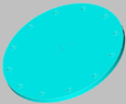
Large ceramic disc about 1.5" thick and about 24" in diameter on a rotary. On the top side the disc has machined casting molds. Each mold will get a room temp slug of lead of proper volume. Inductive heating will melt the lead so it can take shape of the mold.

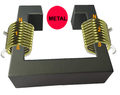
The idea for coils is to have two of them, "iron" core. One will be held directly over the lead slug, and one held directly below the lead slug on the bottom side of the plate. The coils are driven ontop/offbottom offtop/onbottom. In essence, they flip-flop the magnetic field at 10kHz. Coils are driven so the the magnetic field direction is "the same", into the part (one down into the part, one up into the part), So technically, the eddy current induced in the part changes direction 180deg at frequency, thus heating the lead to melt.

So, my questions are:
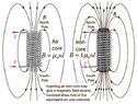
  1. Is iron core coil better than air core for this application when it comes to focusing the magnetic field at the poles as the mag field leaves the ends to wrap around?
  2. Most of the inductive heating coils I see that heat parts, the part is inside the coil. Does inductive heating still work if the part is not inside the coil?
 
  • Like
Likes Delta2
Physics news on Phys.org
  • #2
Iron core has "more" magnetic field (higher mag flux) coming straight out the poles, like this? So works better for my application? Coils will be driven around 40 amps (50% duty cycle).
 

Attachments

  • iron-air.jpg
    iron-air.jpg
    42.5 KB · Views: 109
  • #3
You're probably OK here on the classical physics forum.

Or click REPORT and ask the mentor to move it to the Electrical Engineering forum.
 
  • #4
Welcome to PF.
10 kHz to 100 kHz will have skin effects.

In lead the depth will restrict heating to the outside.
Lower frequency eddy currents will penetrate deeper.

So what weight is the lead slug and how deep will the ? kHz heating be?
You might do better melting flat coins of lead than slugs.

A laminated iron core will not work above 10 kHz.
You will need to close the magnetic circuit with an iron powder or a ferrite material.

The device may need to be enclosed in a carefully designed "reflective" copper stove or hood so the radiation stays in the oven volume. That may reduce the need for the magnetic core.
 
  • #5
Let me clarify, it will likely be a ferrite core inductor, and setup like this (illustration purposes). Ferrite cores can work ok well into MHz area. When left coil is 'on' the mag field leaves to right into metal, when right coil is 'on' the mag field leaves to left into the metal. So, object is not inside the coil, just in close proximity to the poles.
The lead blank can be whatever shape of some volume. As for skinning and heating, the coils remain on for a period of time until the lead heats to fully melt.
coils1.png
 
  • Like
Likes Delta2
  • #6
I think there is one hidden problem with this more open geometry. The actual field (and hence the induced heating rate) will depend more strongly on the exact shape and size of the sample. If different molds are sequentially within one disc, each may heat differently even with the same electrical input. Care will be needed.
 
  • #7
@MagneticMagic I would suggest using the coils in one of the axis , say top-bottom and then additionally using a small motor that has a powerful neodymium magnet attached to it's rotor, such a rotating strong B field would help to stir the already molten parts of the metal to make the whole mold more even during melting.
A local company here use the same technique and sell it for large aluminum smelters.

But without seeing the mold it is hard to say more clearly.
You do not need a magnetic core for your coils , yes the field will be weaker that way but as long as you can put the metal within the coil it will work, like see induction heating clips on youtube, they usually have an air coil and put the metal inside the coil, Your coil will most likely need water cooling so it is convenient to make it out of a copper plumbing tube. Depending on how big your mold is you can think about this idea.
 
  • #8
I will make share a CAD illustration of the mold and disk. With a disk I can't get the metal inside the coil.

As for controlling mag field, I initially had something like this. My concern here was, kinda looks like a isolation transformer, and I did not want to couple the two coils. Wondering is wrapping the coils with mu metal would help to block the transformer effect?
 

Attachments

  • coil-ring.png
    coil-ring.png
    23.8 KB · Views: 91
  • #9
MagneticMagic said:
My concern here was, kinda looks like a isolation transformer, and I did not want to couple the two coils.
Sorry, that makes no sense to me. Of course you want to have the coils working together. You show opposing North ends, but you should reverse the notation on the right coil so that a current through both coils generates the same field direction. You want a net B-field to go through your sample, right?
 
  • #10
The coils are not 'on' at the same time. Opposed coils is what it should be, heating by eddy current happens by flipping the eddy current direction in the part, this mean you need flipping magnetic field vector. To do that with two coils driven 50% PWM the only way to flip the mag field in the part is to drive N pole into the part from one side (left), then drive N pole into the part from the other side (right) of the part. In other words, two mag field vectors 180deg from each other, but they don't exist at the same time.

Electrically, I am taking the typical induction heater single coil driven by AC and creating the same using DC and two coils. Doing it in DC gives me more flexibility for several other operating parameters.

As for the mold, it's something like this pic. The rotary would rotate the disc and stop when the part is under the coil, dwell some time to melt the metal, then rotate and repeat.
 

Attachments

  • disc.png
    disc.png
    8.8 KB · Views: 93
  • #11
MagneticMagic said:
The coils are not 'on' at the same time. Opposed coils is what it should be, heating by eddy current happens by flipping the eddy current direction in the part, this mean you need flipping magnetic field vector.
No, that is not how you generate eddy currents. You generate eddy currents by driving a B-field through the metallic part. To maximize the AC B-field, you drive both coils at the same time with the same AC voltage waveform so that they both make the same AC B-field at the same time.

What is your background with magnetics and electronics?
 
  • Like
Likes nasu
  • #12
Ideally a single coil would be wound close around the lead slug. If you cannot do that then two coils, one above and one below, in a Helmholtz arrangement, will cause eddy currents in the lead. Those two coils should be in phase, and be tuned to resonance as part of the oscillator.

The way it is now designed is so the field in the middle will alternate with high harmonic content. Turning a coil on and then off is very inefficient. It is much better to tune the coil inductance to resonance with a high voltage capacitor. That way energy not lost to the lead on this cycle will be recirculated to try again on the next cycle. It then does not need a core.

The presence of the lead will slightly lower the inductance, so raise the resonant frequency of the tank circuit, which will not matter if the tank is part of the oscillator. You might consider operating in the 27 MHz ISM band like other induction furnaces, diathermy units and dielectric welders.
 
  • Informative
  • Like
Likes hutchphd and berkeman
  • #13
Baluncore said:
Those two coils should be in phase, and be tuned to resonance as part of the oscillator.

Yes. If the decision is made to use (probably cooled?) ferromagnetic (ferrite) cores then I believe the "horsehoe magnet" core configuration shown in the picture likely makes sense. But certainly the faces should be opposite poles (with the coils in phase).
 
  • #14
Tank circuits are limited in ability to change frequency.
Flipping the mag field using two coils increases efficiency because a mag field is always present in the part (see note below), albeit it flip-flops just like a resonant AC tank ckt. In 50% PWM in a ckt where coil-1 in 'on' when PWM is high, and coil-2 is 'on' when PWM is low, there's really no off time for the mag field, and if it's mag field is same magnitude and direction all the time, then eddy heating won't happen, basically have a strong electromagnet at that point. Flipping the coil mag fields using 50% PWM is about the same as mag field flipping using sine AC. In sine AC the mag field is always there (following sine function) and it flips with the AC. If I drive only one coil with DC PWM there is period of time where there's no nag field at all.

One coil in full H bridge is one method to make "AC" using just DC power source. Aren't induction kitchen stoves H bridge?

Note- driving coil square wave on/off using DC has advantage over sine wave. With PWM DC the B field stays at max longer for the period there is amps in the coil wire. Not the case with AC sine. With two coils in PWM (one on other off, then flip flop), the B field appears to always be at max, albeit opposite vectors.

I have seen several other applications melting 20lb lead ingots in 8"dia ceramic tube using just 10kHz. I don't think I need to be in MHz band, or have to deal with dangerous high voltage. My ckt has max voltage of just 36v, and power supply is just 12vdc.
 
  • #15
Are you saying you are "melting 20lb lead ingots in 8" dia ceramic tube" ?
How will you prevent EMI from harmonics of your H-bridge output ?
 
  • #16
@MagneticMagic I'm sorry but you have to update your EM knowledge, you are missing some basic but important steps.
Eddy currents are just circular currents that form on the surface of a conductor if a B field is applied to it that is time varying.
Sure you can just switch one coil at a time but that will be less effective so there is no real reason to do so.The higher the frequency the less the penetration depth that the B field can achieve before it gets blocked by the surface currents, so yes indeed you don't need Mhz frequencies , 10-30 kHz ir fine for most ferrous metals.
 
  • #17
Baluncore said:
Are you saying you are "melting 20lb lead ingots in 8" dia ceramic tube" ?
How will you prevent EMI from harmonics of your H-bridge output ?
Nope. Small parts in a ceramic rotary disc mold.
I am not using H bridge.
Adjustable PWM drive and some high current FETs. Each coil is 50% duty cycle, but at any given time a B field exists in the part, flip-flopping at frequency just the same like AC drive.
Changing B field at high frequency causes eddy heat, you can do that with sine AC, or using two coils that flip-flop the B field.
 
  • #18
MagneticMagic said:
or using two coils that flip-flop the B field.
B field changes whenever current through a coil changes direction , it doesn't matter whether you have one coil or two coils,
 
  • #19
MagneticMagic said:
Adjustable PWM drive and some high current FETs. Each coil is 50% duty cycle, but at any given time a B field exists in the part, flip-flopping at frequency just the same like AC drive.
You need many turns to get a strong magnetic field.
With voltage drive to an inductance, you will get a half-sine current, the same as with a tank circuit. The current through the inductor will not change efficiently and rapidly.
 
  • Like
Likes hutchphd
  • #20
artis said:
B field changes whenever current through a coil changes direction , it doesn't matter whether you have one coil or two coils,
Not 100% true, B field is a function of the amps vector. Amps Magnitude and direction defines the B field at any given time. When the amps direction changes 180deg, the poles swap position.

AC amps varies as function of sine, or whatever AC function you use.

Two coils back to back like NS-NS will create a B field that is same B flux direction. But, two coils back to back like NS-SN will creating opposing B field. How can that be, amps at any given time are flowing in one direction only. Well, physical coil construction/orientation matters. With a series NS-SN confiuration, the amps are not flowing the same way around the coil, in fact the amps are 180deg opposite around the coil, even though actual amps end-to-end is in one direction. A fun experiment is, create a CT transformer, but on the secondary CT side, wrap the coils in one direction, and then at the CT wrap the coils for 2nd half in opposite direction.
 
Last edited:
  • #21
Baluncore said:
You need many turns to get a strong magnetic field.
With voltage drive to an inductance, you will get a half-sine current, the same as with a tank circuit. The current through the inductor will not change efficiently and rapidly.
I am able to turn on and off (amps, zero to max) of ferrite core 7.5uH within 3-4 usec, coil carrying 10amps, PWM 50% 10kHz. I am not operating in MHz+, etc.

Some of the online vids of homemade induction heaters using LC tank ckts are funny. One kid built a working heater, goes on to heat up an end of steel flat stock within seconds, 3" x 1/4", and then blurts out "wow, there's 96kW going into the metal". Hmmmm, he had machine plugged into 120vac outlet, so where is 96kW coming from. It's magic, lol.
 
Last edited:
  • #22
I wish you good luck. You will need it.
 
  • Like
Likes nasu and berkeman
  • #23
MagneticMagic said:
I am able to turn on and off (amps, zero to max) of ferrite core 7.5uH within 3-4 usec, coil carrying 10amps, PWM 50% 10kHz. I am not operating in MHz+, etc.
Then why not double the number of turns and halve the current ?
What limits the coil current ?
 
  • #24
Baluncore said:
Then why not double the number of turns and halve the current ?
What limits the coil current ?
Within a freq range I can increase L, but there's a max L where rise time of the mag field gets too close to freq, so it ends up chopping and not reaching max B field.
 
  • #25
hutchphd said:
Yes. If the decision is made to use (probably cooled?) ferromagnetic (ferrite) cores then I believe the "horsehoe magnet" core configuration shown in the picture likely makes sense. But certainly the faces should be opposite poles (with the coils in phase). I wish you good luck. You will need it.
The drive looks like this (animation gify). The faces would always be opposite poles, but the poles flip at freq. And since it's DC drive the B field is always max at any given time.

No luck being used. Magnetics/Physics converted into electrical ckt.
 

Attachments

  • coil-ring-animation.gif
    coil-ring-animation.gif
    30.3 KB · Views: 120
Last edited:
  • #26
So you only use half the coil just to avoid the H driver? I reiterate my wishes for good luck. Or you could learn the Physics. Your choice.
 
  • #27
MagneticMagic said:
Within a freq range I can increase L, but there's a max L where rise time of the mag field gets too close to freq, so it ends up chopping and not reaching max B field.
Yes, max_L is a limit. The other current limit is saturation of a core. If you have a core it must have a wide airgap about the hot lead slug. So why bother with a core, just use a Helmholtz coil pair as a resonant tank. A core also increases inductance, which you don't want there. If you can keep the sinewave below 100 kHz you should avoid radio interference.
 
  • Informative
Likes berkeman
  • #28
MagneticMagic said:
The faces would always be opposite poles, but the poles flip at freq. And since it's DC drive the B field is always max at any given time.
How could the poles not flip at frequency? How can the B field be max at "any given time" if you use switches to switch the current through coils ?
What do you think happens to a DC current as it is being switched through a inductance?

Why do you think @Baluncore suggested the resonant circuit approach?PS. I think I now understand how you look at this , you use two separate coils so that as you switch one coil on it creates a B field that reaches it's maximum at some point and before that point you already switch the other coil on and so the second coil reaches it's maximum B field while the first coil is still on and also has the max B field and only then when the second coil has reached it's max B field you switch the first coil off. also the fields from each coil are the same polarity facing the metal.

1) First of all having such an arrangement will heat the ends of the metal facing the coils more than the middle because the opposing field will cancel out in the middle,
2) Secondly you will need more current because each coil field is opposing the other field and so the total field will be less than what it could be if both coils worked in "unison" with a NS-NS arrangement.

If this is so , then I think it's just a waste of current , the heat within the metal comes from the "change in B field" it's essentially induction, you change the B field and as it changes a circular current is induced on the surface of the metal as the B field tries to enter the metal. The moment the B field becomes static aka doesn't change anymore no more currents are induced.
The idea of the two coils in series with a resonant circuit and a single B field is simple the B field never stops changing (maybe for a brief brief moment during the peak of each half period) and this way you get a continual induction and eddy currents on the surface.
I think your approach is simply worse (less informed) and not as effective , current will be wasted somewhat.

Induction is really a mature technology there is nothing new there , the stuff that works has been known for a long time by now, probably longer than you are alive, I suggest you take the approach given here by other members, not that your approach will not work it's just less effective, but then again I see your nickname contains the words "magic" so what do I know...
:biggrin:
 
  • Like
Likes hutchphd
  • #29
I think I can see what @MagneticMagic is attempting to achieve here.
Since the two coils are on the same magnetic core, the coils will actually appear to be the centre-tapped primary of a transformer, with the metal charge eddy current as the secondary. The primary is driven class B, with 50% duty cycle, by a phase inverted pair of MOSFETs.
It seems that MagneticMagic has reinvented the push-pull transformer coupled output stage, only about 125 years too late to claim novelty.
https://en.wikipedia.org/wiki/Push–pull_output
 
  • Like
Likes hutchphd
  • #30
Baluncore said:
It seems that MagneticMagic has reinvented the push-pull transformer coupled output stage, only about 125 years too late to claim novelty.
I never claimed I invented a new way. There are several ways to construct inductive heating physically and using various circuits for control.

I have a simple 60Hz transformer that can dish out over 1000amps on the secondary, but it's still limited to just 2.4kW. Obviously this is a heavy setup, and secondary wire still gets hot even though it's 5/8" diameter wire.

I'll be playing around with some configurations in my work lab.
 
  • #31
I (foolishly) assumed you were looking for an optimal solution. If there are no design requirements then you have no real need to understand anything..
 
  • #32
artis said:
How could the poles not flip at frequency? How can the B field be max at "any given time" if you use switches to switch the current through coils ?
What do you think happens to a DC current as it is being switched through a inductance?
3-4usec is their fall time, slightly slower rise time. Since the two coils are driven 180 out of phase 50% PWM and the "off" time per cycle is ~3-4usec, the B field is "always on". In other words, the B field will very abruptly switch poles very very fast, only takes ~6usec to flip. In a LC tank the flipping of B field is way more gradual per cycle, sine wave gradual. Time wise, with 1kHz drive, full "on" time for each coil per cycle is 1ms/2 - 4usec. So in other words, "always on".
 
Last edited:
  • #33
artis said:
change the B field and as it changes a circular current is induced on the surface of the metal as the B field tries to enter the metal. The moment the B field becomes static aka doesn't change anymore no more currents are induced.
So are you talking about dB/dt ?
In AC analysis the B field simply flip flops at some frequency, yet depending on the wave used dB/dt can be very very different. Sine wave is "slow", square wave is "fast". Frequency alone of the B poles flipping is not the whole story.

dB/dt has profound effect on eddy current heating. In sine you have some "avg" (rms) B field over 1/2 cycle, because the B field grows and shrinks to the beat of sine. Let's assume Bmax = 10, so rms would be 0.707, in 1kHz (per half cycle) you get 0.707/0.5ms. Take that to DC PWM where I can switch on/off from Bmax (10) in usec. dB/dt is many magnitudes greater with PWM.

Here's 10kHz. The upper is the PWM drive source, the lower shows the two coils. dB/dt is magnitudes higher than sine wave. Yeah, on is a bit slower than 4usec, darn silicon.
 

Attachments

  • Capture.PNG
    Capture.PNG
    2.9 KB · Views: 90
Last edited:
  • #34
MagneticMagic said:
the B field is "always on". In other words, the B field will very abruptly switch poles very very fast, only takes ~6usec to flip. In a LC tank the flipping of B field is way more gradual per cycle, sine wave gradual.
So explain in your own words then , what is the benefit in this?

Do you know that a square wave actually has multiple sine wave components/harmonics in it , you will get the combined effect of if you just used a higher sine frequency, trying to "square" everything will also add more heat to the work coil itself.
And yes FET's work in on/off modes naturally but if you will use a sufficiently large coil/inductance your real waveform within the coil will approximate sine anyway, that's just natural you can't escape it.

You are going the opposite way, instead of having a field that constantly varies (yes with slower rises and falls) you want to have a field that quickly jumps up and down but stays static inbetween, if you actually look at the waveform graph you should notice that most of the time within a square wave is spent either at max voltage or no voltage while in sine almost all time is spent in a varying voltage mode.
Whenever the voltage reaches a steady level you essentially have steady current passing through the coil, a steady current does not produce a changing magnetic field so a steady current through the work coil is just wasted current as it does not accomplish any goal.

In induction heating you want to just constantly shuffle a B field back and forth and make it penetrate further into the target metal in the least amount of time so you would look for the most efficient way to do that which consumes least energy in the process of doing so. Resonance here accomplishes just that.
But again as I said maybe I'm dead wrong so you are free to explain and prove your method is better than the ones used by most
 
  • #35
artis said:
Whenever the voltage reaches a steady level you essentially have steady current passing through the coil, a steady current does not produce a changing magnetic field so a steady current through the work coil is just wasted current as it does not accomplish any goal.
Worse! It then causes ohmic heating in the copper to no benefit.
 
  • Like
Likes artis
<h2>1. What is inductive heating?</h2><p>Inductive heating is a process in which an alternating electrical current is passed through a conductive material, creating a magnetic field that induces eddy currents within the material. These eddy currents generate heat, which can be used for various industrial and domestic applications.</p><h2>2. How does inductive heating work?</h2><p>Inductive heating works by passing an alternating current through a coil, which creates a changing magnetic field. This magnetic field then induces eddy currents in a nearby conductive material, causing it to heat up due to resistance. The heat generated is proportional to the strength of the magnetic field and the electrical conductivity of the material.</p><h2>3. What are eddy currents?</h2><p>Eddy currents are circular electrical currents that are induced within a conductive material when it is exposed to a changing magnetic field. These currents flow in a direction that is perpendicular to the magnetic field and result in the generation of heat due to resistance.</p><h2>4. What are some applications of inductive heating and eddy currents?</h2><p>Inductive heating and eddy currents have a wide range of applications, including induction cooking, metal heating and melting, induction brazing and soldering, and heat treatment processes. They are also used in induction motors and generators, as well as in non-destructive testing methods.</p><h2>5. What are the advantages of using inductive heating compared to other heating methods?</h2><p>Inductive heating offers several advantages over other heating methods, including precise and localized heating, high energy efficiency, and faster heating rates. It also eliminates the need for direct contact between the heat source and the material being heated, making it a safer and cleaner option. Additionally, inductive heating allows for better temperature control and can be easily automated for industrial processes.</p>

1. What is inductive heating?

Inductive heating is a process in which an alternating electrical current is passed through a conductive material, creating a magnetic field that induces eddy currents within the material. These eddy currents generate heat, which can be used for various industrial and domestic applications.

2. How does inductive heating work?

Inductive heating works by passing an alternating current through a coil, which creates a changing magnetic field. This magnetic field then induces eddy currents in a nearby conductive material, causing it to heat up due to resistance. The heat generated is proportional to the strength of the magnetic field and the electrical conductivity of the material.

3. What are eddy currents?

Eddy currents are circular electrical currents that are induced within a conductive material when it is exposed to a changing magnetic field. These currents flow in a direction that is perpendicular to the magnetic field and result in the generation of heat due to resistance.

4. What are some applications of inductive heating and eddy currents?

Inductive heating and eddy currents have a wide range of applications, including induction cooking, metal heating and melting, induction brazing and soldering, and heat treatment processes. They are also used in induction motors and generators, as well as in non-destructive testing methods.

5. What are the advantages of using inductive heating compared to other heating methods?

Inductive heating offers several advantages over other heating methods, including precise and localized heating, high energy efficiency, and faster heating rates. It also eliminates the need for direct contact between the heat source and the material being heated, making it a safer and cleaner option. Additionally, inductive heating allows for better temperature control and can be easily automated for industrial processes.

Similar threads

  • Electrical Engineering
Replies
6
Views
1K
  • Introductory Physics Homework Help
Replies
3
Views
964
  • DIY Projects
Replies
10
Views
2K
  • Electromagnetism
Replies
1
Views
557
  • Electromagnetism
2
Replies
42
Views
563
Replies
1
Views
1K
  • Introductory Physics Homework Help
Replies
6
Views
658
  • DIY Projects
Replies
2
Views
2K
Replies
14
Views
3K
Replies
4
Views
883
Back
Top