Inductor Circuit Simulation: Understanding Current Rise and Voltage Output

Join the discussion
Ask a follow-up here, or get your own question answered by working scientists, mathematicians and engineers — people, not an autocomplete.
Real named experts · corrections over time · the nuance an AI answer skips
5 replies · 2K views
PhysicsTest
Messages
260
Reaction score
27
TL;DR
To understand the inductor circuit.
I am trying to understanding the inductor circuit. I have drawn the below circuit and try to simulate
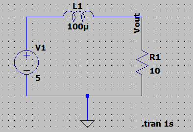
1635602554158.png

The Inductor current comes to 500mA and Vout is 5V as per simulation. The current in inductor should slowly increase from 0A to 500mA but i cannot see that in the waveform. Is my understanding correct?
 
Engineering news on Phys.org
PhysicsTest said:
but i cannot see that in the waveform
Neither can we. What waveform ?
Do you have some equations to describe the behaviour of your circuit ?

##\ ##
 
Reply
  • Like
Likes   Reactions: PhysicsTest
1635604571909.png

This is the output waveform i can get. Ok now i started writing the equation for the circuit.
##i(t) = \frac{V} {R} (1 - e^{\frac{-Rt} L})##
Substituting the values
##i(1) = 5/10*(1 - e^{-10^5}) ##
##i = 0.5A##. The answer is matching.
 
Reply
  • Like
Likes   Reactions: BvU
The DC analysis sets up 500 mA before the run.
You must use; V1 pulse; initial=0V; Von=5V; Tdelay=5usec;
and .TRAN stop time = 100 usec.
Then see the current rise over about 50 usec.
Inductor.png
 
Last edited:
Reply
  • Like
  • Informative
Likes   Reactions: BvU, PhysicsTest and berkeman