Mech_LS24
- 148
- 16
Thanks @jrmichler , really appreciate your help. I am working on your last comment, expect coming back to you tomorrow.
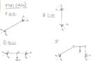
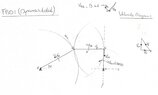
The discussion revolves around the influence of friction in a structure with multiple pivot points, specifically comparing deep groove ball bearings and plain bearings. Participants explore calculations for friction losses, the impact of bearing types on movement, and the complexities involved in accurately determining friction in mechanical systems.
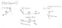
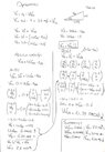
Participants express differing views on the proper methods for calculating friction at joints, with some advocating for specific multi-step approaches while others question the initial assumptions and calculations presented. No consensus is reached on the best method or the implications of the friction calculations.
Participants highlight the complexity of calculating friction in mechanical systems, noting that factors such as bearing type, load distribution, and angular velocity all play significant roles. There are unresolved questions regarding the assumptions made in initial calculations and the definitions of terms used in the discussion.