Is My Blender Motor Viable for a Rotary Tool Shaft Mod?

  • Thread starter Thread starter theycallmevirgo
  • Start date Start date
  • Tags Tags
    Blender Motor
Click For Summary
SUMMARY

The discussion centers on the viability of using a Ninja blender motor (model ss351) for a rotary tool shaft modification. Key points include identifying whether the motor is brushed or brushless without disassembly, testing the motor using a bench power supply, and the potential for continuous speed and torque control with a foot pedal. Participants suggest troubleshooting steps for power issues, including checking the power cord, inspecting circuit boards, and verifying capacitor connections.

PREREQUISITES
  • Understanding of brushed vs. brushless motor technology
  • Familiarity with basic electrical troubleshooting techniques
  • Knowledge of circuit board components and their functions
  • Experience with bench power supplies and motor testing
NEXT STEPS
  • Research methods to identify brushed vs. brushless motors
  • Learn how to test DC motors with a bench power supply
  • Explore circuit design for speed and torque control using foot pedals
  • Investigate the role of capacitors in motor operation and troubleshooting
USEFUL FOR

Electronics enthusiasts, DIY hobbyists, and anyone interested in motor modifications or troubleshooting electrical components.

theycallmevirgo
Messages
108
Reaction score
25
TL;DR
How can I test and repurpose a consumer kitchen motor with limited information?
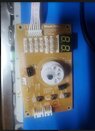
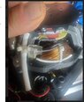
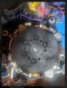
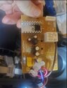
I got a new Ninja blender (model ss351) a few months back that was DOA. The manufacturer sent a replacement immediately, but I found a blog post on hackaday showing a simple mechanical mod that would enable me to use the motor to drive a flexible rotary tool shaft (Dremel etc). The attached images are the motor, the control board and the power board. The purple wire to the control board is directly from the wall outlet.

Simple questions;

How can I tell if the motor is brushed or brushless without disassembling it any further?

How can I test the motor itself to make sure it wasn't the specific component that failed? Will simply driving it from a bench psu do it? What minimun V/I?

Is this motor viable for this application? Optimally, I'd like continuous speed/torque control with a foot pedal. I'm not scared of building a circuit from scratch (_yet_).

If not viable, can I use it for a pedal powered generator?

I can link to the hackaday post and the rotary tool shaft if necessary. Also, obviously please let me know if additional pictures are needed.

Thanks so much in advance

JoePS - the motor pic with my thumb in it is odly distorted. The plastic disc on top is at least 4x the size of my thumb and the plastic cylinder immediately below the ziptie is about half the size of my thumb.
 

Attachments

  • blender_motor.jpg
    blender_motor.jpg
    36.4 KB · Views: 175
  • blender_control.jpg
    blender_control.jpg
    34.9 KB · Views: 199
  • motor_a.jpg
    motor_a.jpg
    37.2 KB · Views: 197
  • motor_b.jpg
    motor_b.jpg
    45 KB · Views: 200
  • blender_power_board.jpg
    blender_power_board.jpg
    35.7 KB · Views: 204
Physics news on Phys.org
Very unlikely that the motor has brushes. Here are some images of motors with brushes.
https://www.google.com/search?tbm=i...r+in+dc+motor&gbv=2&oq=brushes+and+commutator

Is there ANY activity at all when you turn it on?... Motor humming, any LEDs (lights) coming on?

1) If not,
Could be a bad power cord.
check that incoming power is getting to board(s).​
trace wiring from power cord to any switch, fuse, or connector to first board it connects to​

2) If motor hums but doesn't turn AND there are three wires to the motor AND there is a somewhat large capacitor (usually not mounted on a circuit board), the capacitor should be connected to the motor and a circuit board.

2A) Verify its wiring to motor, it is Usually connected to two motor wires, and one of those motor wires will connect only to the capacitor and the other motor wire will also connect to other circuits on the circuit board.​
2B) If the capacitor exists, it may be wired to a circuit board and connected to the motor by the board.​
2B1) the capacitor could be defective, or may be an open connection to, or in, the motor.​

3) If the motor does not hum, everything completely dead:
There is probably a bad component on, or bad connection to, a circuit board. This will require detailed troubleshooting on your part, the first step of which is close visual inspection of the boards and all connectors.​
3A) Then you draw a schematic diagram of the circuitry to understand its intended operation and start troubleshooting at the component level.​

Cheers, (and good luck!)
Tom
 

Similar threads

  • · Replies 3 ·
Replies
3
Views
2K
Replies
5
Views
3K