Discussion Overview
The discussion revolves around logic circuits and truth tables, specifically focusing on writing equivalent logic expressions for given circuits, constructing truth tables for inputs A, B, and C, and determining if the expressions yield the same outputs. The scope includes technical explanations and mathematical reasoning related to logic gates.
Discussion Character
- Technical explanation
- Mathematical reasoning
- Debate/contested
Main Points Raised
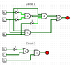
- Participants discuss how to derive logic expressions from circuit diagrams, with suggestions to start with simpler circuits.
- Some participants explain the functions of different logic gates, including NOT, OR, AND, and NAND gates, and their respective outputs based on inputs.
- There is a proposal for the logic expressions for two circuits, with one participant questioning the correctness of their expressions and truth tables.
- A participant points out an error in the expression for circuit 1, noting that a NAND gate's output requires taking the complement after the AND operation.
- Another participant suggests a corrected expression for circuit 1 and asks for the truth table based on this correction.
- Discussions include checking the correctness of truth tables and comparing outputs of the two circuits to determine if they are equivalent.
- Some participants express uncertainty about whether the two circuits are indeed equal and seek confirmation on their findings.
Areas of Agreement / Disagreement
Participants generally agree on the process of deriving logic expressions and constructing truth tables, but there are disagreements regarding specific expressions and whether the circuits are equivalent. The discussion remains unresolved on some aspects, particularly concerning the correctness of the expressions and the final outputs.
Contextual Notes
Limitations include potential misunderstandings of gate functions, the need for clarification on the NAND gate's role, and the accuracy of truth tables based on derived expressions. Some mathematical steps remain unresolved, particularly in simplifying expressions.